Demonstration course · not for use in operating a crane. Supervised practice, independent evaluation and employer authorization remain separate.
How to use this manual. Read the component explanation, source figure and decision example together. This reading companion does not include scored questions.
Reference-only load chart library
Read before using: REFERENCE ONLY — This public chart is for recognition and chart-reading practice. It is not an issued in-cab chart, a serial-matched rating, or operating authorization. Confirm the current serial, revision, attachment, counterweight, boom or jib, reeving, deductions, support condition, operating area, and machine condition before any lift.
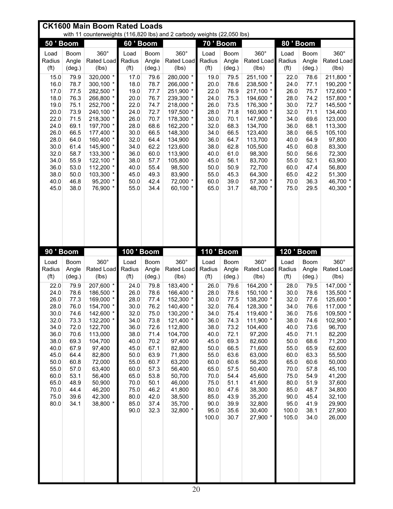
Public CK1600 chart book · PDF p20
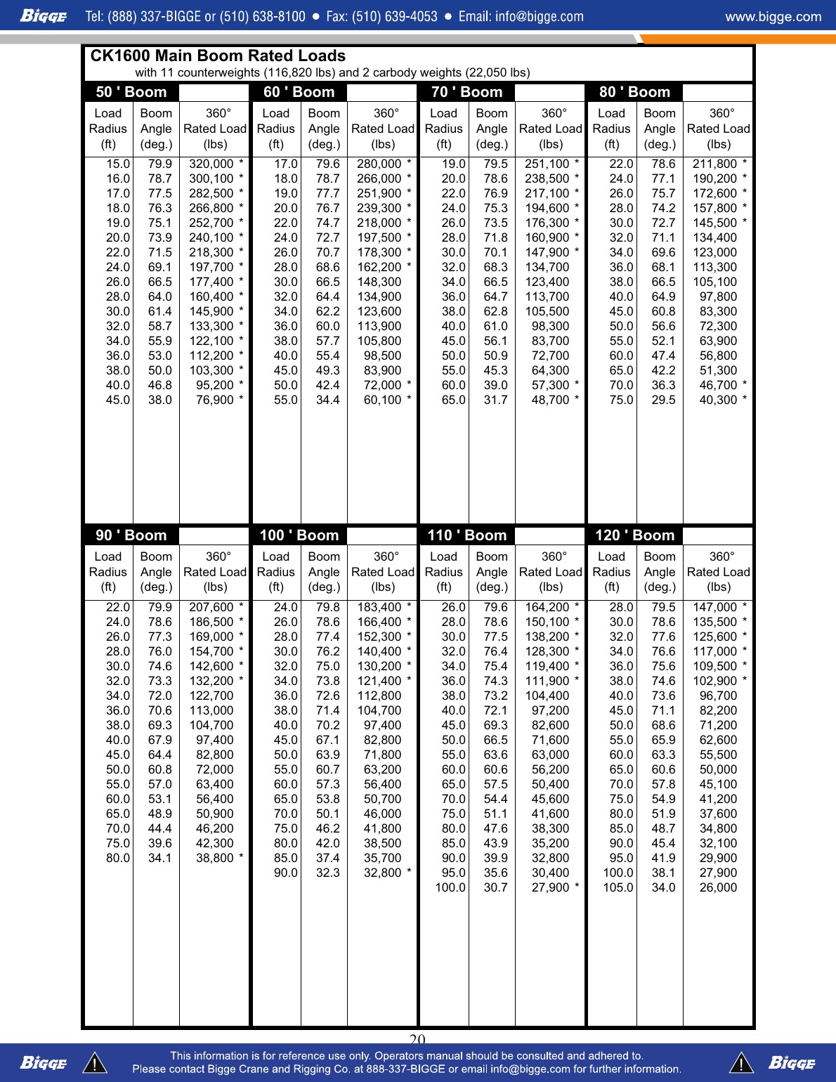
Main boom rated loads; 116,820 lb counterweight; 22,050 lb carbody weight; public CK1600 chart book.
Main boom rated-load table. Read the heading, counterweight/carbody configuration, radius, boom length, and notes as one record.
Each image is a complete rendered source page. Retrieval date, page, configuration, source URL, and hashes are recorded in ../shared/open-source-load-charts.json.
The failure this Area is built against is specific: an operator who has run a machine for years and has never opened its manual. He knows the crane by feel. He is also, quietly, working from remembered numbers that may belong to a different machine.
What you will be able to do
Find any governing fact in under two minutes. Say which document outranks which. Read this machine's name plate and state what configuration it is in right now — not what it was in last week.
The knowledge check
Seven questions at the end make up the knowledge check, all on critical points. It requires 100%. There is no partial credit and the correct answer is not shown on a miss.
This machine is governed by more than one book, and the most common mistake is looking for a number in the wrong one.
Focus viewVerify model, serial applicability, book code, and print date here.
The manual cover identifies the CK1600, its applicability from serial GN03-02001, book code S2GN00003ZE10 (C), and May 2007 print date. Source: CK1600 O&M PDF p1, cover and applicabilityOpen the complete controlling page
Document
Answers
Identifier
Operation & Maintenance manual
How to operate, inspect, assemble, maintain
S2GN00003ZE10 · 2007-05
Spec book / capacity charts
What it may lift, and in what configuration
CK1600 Spec Book · 2004-07
Service / parts manuals
Repair procedures and part numbers
not carried in the cab
LMI memory card
The rated load the controller looks up
in the controller slot
The one that catches people
The Operation & Maintenance manual contains no rated capacity chart. Not one. If you are looking for a capacity in the O&M manual you will not find it, and if you think you have, you are reading a specification, not a rating.
Rated load for this machine comes from the spec book and the LMI, never from the O&M manual.
Focus viewMain boom rated loads by boom length, load radius and boom angle, for the counterweight and carbody weights in the heading. Ratings live here and on the controller memory card, not in the O&M manual.
The chart heading, radius, angle, gross rated load, and structural-limit marks must be read as one record. Source: Supplied CK1600 Spec Book PDF p21, main-boom rated loadsOpen the complete controlling page
Spec book
Supplemental data and deductions p20 · Main boom rated loads p21–23 · Jib rated loads p24–29 · Working range diagrams p17–19 · Boom and jib arrangement p16 · Winch performance and rope p6
LMI controller
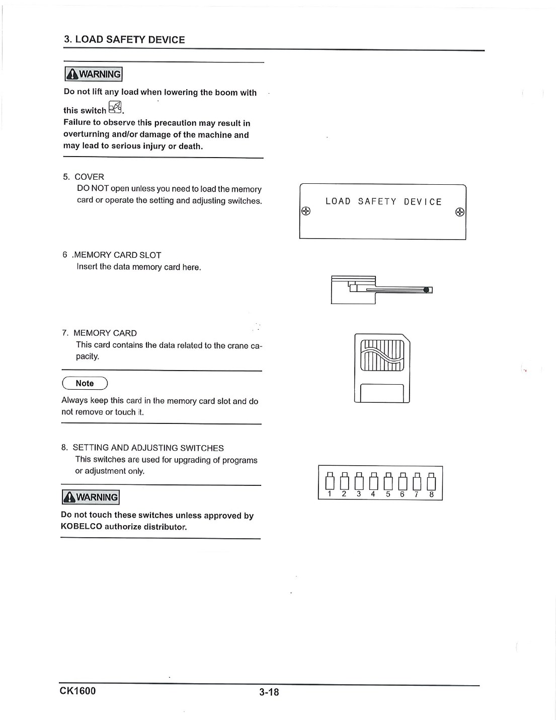
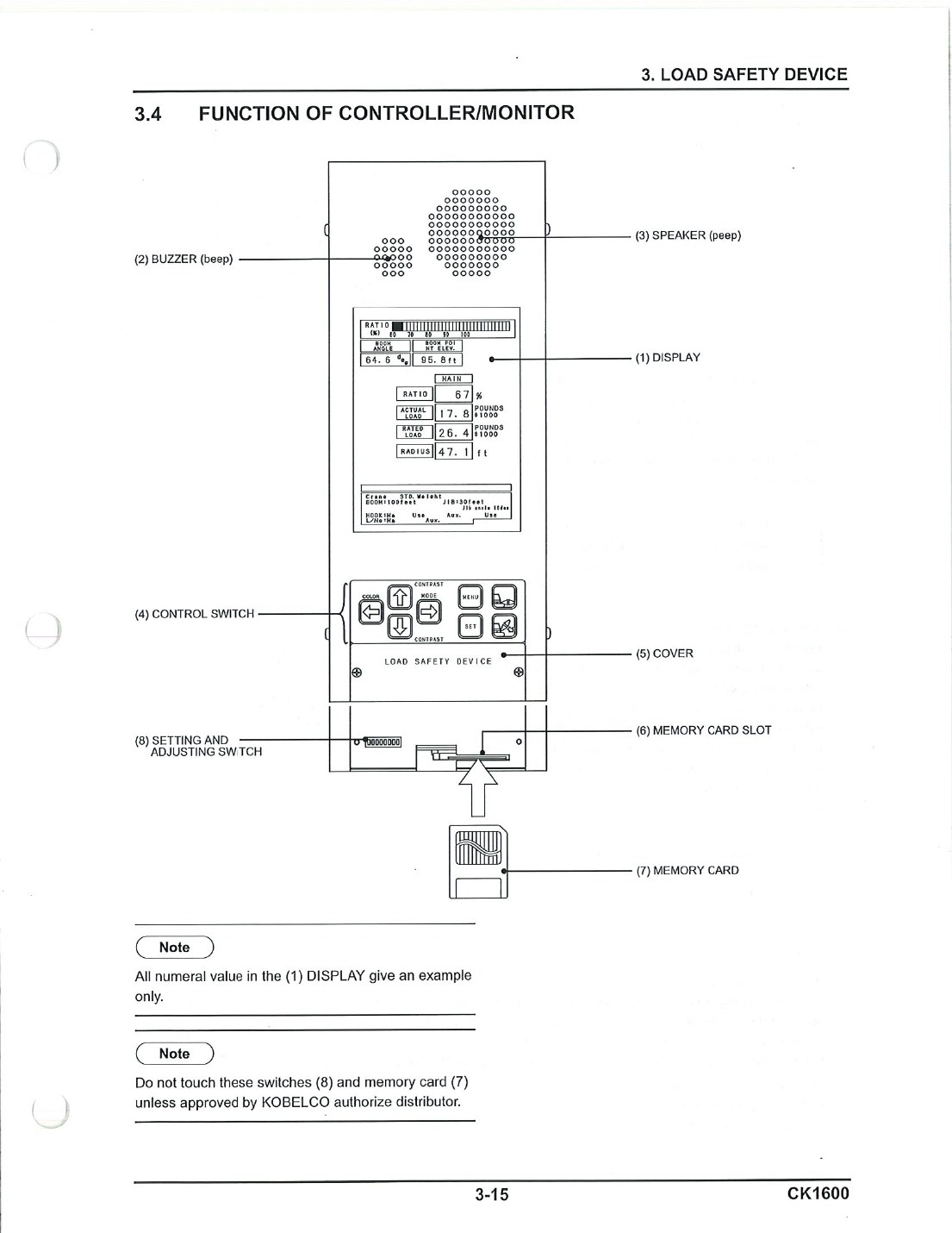
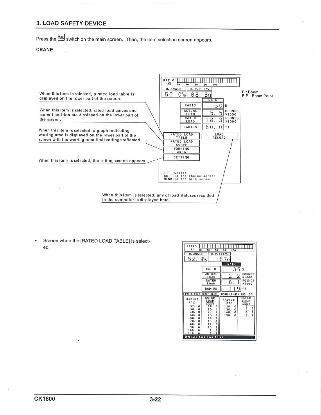
RATED LOAD TABLE and RATED LOAD CURVE screens read from the memory card kept in the controller slot. The card holds the crane capacity data. Do not remove or touch it.
Spec Book PDF p16–29 · O&M PDF p105, p109Reference O&M p105
Everything downstream — which manual, which chart, which parts — hangs off the serial number stamped on the name plate.
Focus viewAPPLICABLE: from GN03-02001. Compare it with the serial stamped on the name plate; a machine below that serial needs a different book.
The manual cover identifies the CK1600, its applicability from serial GN03-02001, book code S2GN00003ZE10 (C), and May 2007 print date. Source: CK1600 O&M PDF p1, cover and applicabilityOpen the complete controlling page
Model
CK1600
Serial
GN03-xxxxx
Engine no.
P11C-xxxx (Hino P11C-UN)
Hours
hourmeter, gauge cluster
Quote the serial and the total hours from the hourmeter whenever you order parts or request service.
Applicability
This manual is marked APPLICABLE from GN03-02001. A serial below that range is a different book and, potentially, different charts.
The controller computes rated load from the configuration you enter, looked up against the memory card. It does not sense the machine's configuration for you.
The manual identifies the memory card as the crane-capacity data source and restricts access to authorized service. Source: CK1600 O&M PDF p105, capacity memory cardOpen the complete controlling page
Maximum rating
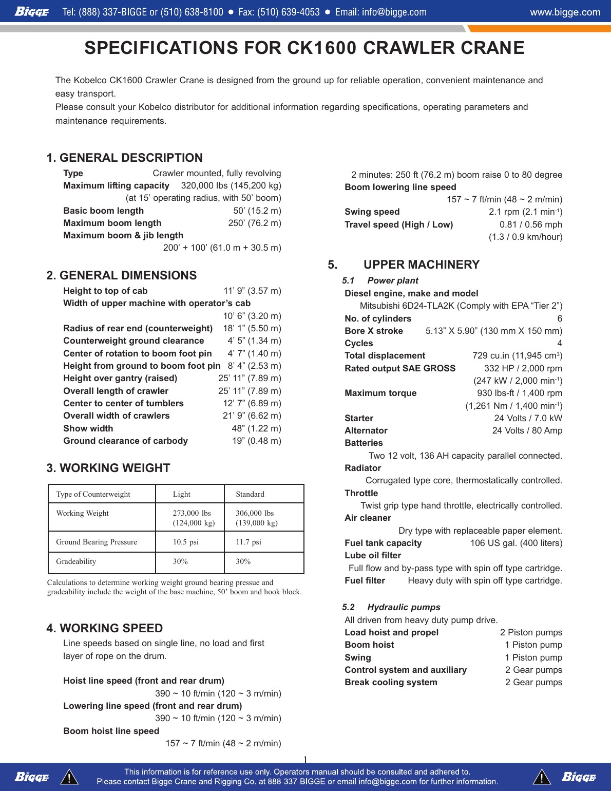
320,000 lb at 15 ft radius on the 50 ft standard boom — the single largest number this machine has, and true only in that one configuration.
Check on your crane
Where the printed capacity chart is carried on this specific machine has not yet been confirmed, and it must be checked against what the memory card holds.
Spec Book PDF p2 · O&M PDF p105, p109Reference O&M p105
This machine ships in two arrangements. They are not small variations — they change working weight, ground bearing pressure, and what the machine may legally lift.
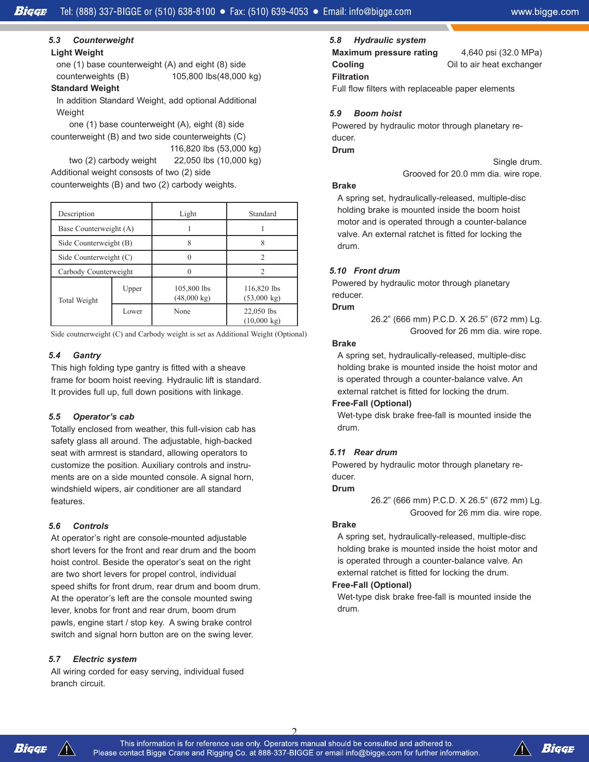
Light and Standard counterweight arrangements differ; the course must never infer a Light chart from Standard-chart data. Source: Supplied CK1600 Spec Book PDF p3Open the complete controlling page
Light
Standard
Base counterweight (A)
1 × 17,640 lb
1 × 17,640 lb
Side counterweight (B)
8 × 11,020 lb
8 × 11,020 lb
Side counterweight (C)
—
2 × 5,510 lb
Upper total
105,800 lb
116,820 lb
Carbody weight
none
2 × 11,030 lb
Working weight
273,000 lb
306,000 lb
Ground bearing
10.5 psi
11.7 psi
Read this twice
Every rated load chart supplied for this machine is for the Standard arrangement — 11 counterweights and 2 carbody weights. If this crane is ever worked in the Light arrangement, none of those capacities apply to it.
Lattice boom 50–250 ft · fixed jib 40/60/80/100 ft, mountable only on booms of 90–200 ft · auxiliary sheave on booms of 50–240 ft, maximum 2 parts of 26 mm rope · third drum · reeving winch · hydraulic tagline · translifter · traveling kit · anemometer · lifting height gauge.
Safety service features and optional equipment define what must be confirmed on the actual machine before it is taught as installed. Source: Supplied CK1600 Spec Book PDF p5Open the complete controlling page
Forbidden outright
Any condition exceeding the rating chart · guessing a capacity between charted values (use the next lower rating) · side loading · riding the hook or a load · operating with a release switch held or fixed in RELEASE · lifting anything while lowering the boom out of angle · all-round swing on 53 t of counterweight with no carbody weight · operating the translifter with any counterweight still installed · repairing a cracked hook or shackle by welding.
Spec Book PDF p4, p20 · O&M PDF p10, p14, p18–24, p127–129, p142–144Reference O&M p10
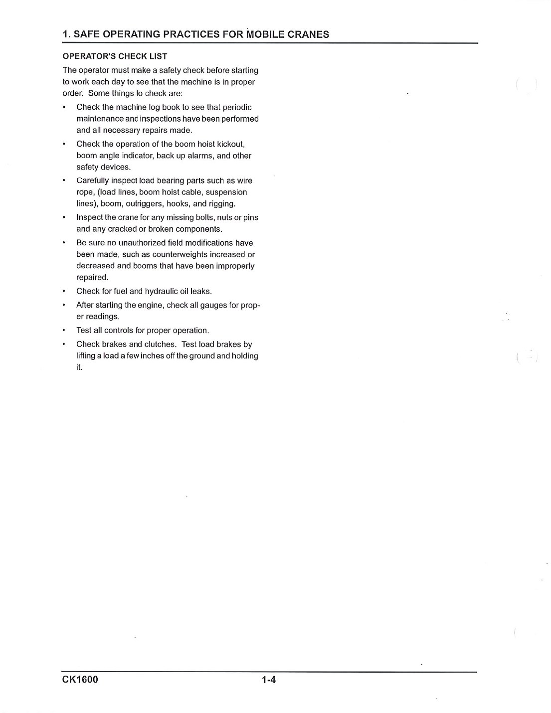
The daily check list opens with a records check: confirm periodic maintenance and inspections have been performed and all necessary repairs made, before you touch anything else.
Interval
Scope
Daily / 8 h
Upper 19 items, lower 3, attachment 11, plus the operator's check list
Weekly / 50 h
Fuel pre-filter water level (option)
Monthly / 100 h
Fan belt, radiator, engine mounts, pumps, motors, valves, drum locks
Quarterly / 250 h
Drive sprocket, idler, upper and lower rollers, slew bearing bolts
Semi-annual / 600 h
Accumulator, frames
2000 h
Hydraulic oil change, 460 litres, filter with it
2 / 4 / 6 years
Boom guy line replacement, by work type — time-based, not condition-based
Yearly
Crack-test every hook and shackle (dye penetrant, MPI, UT or X-ray)
Module 1 was about the documents. This module is about the machine those documents describe — its boom, its hydraulics, its engine, and its rope.
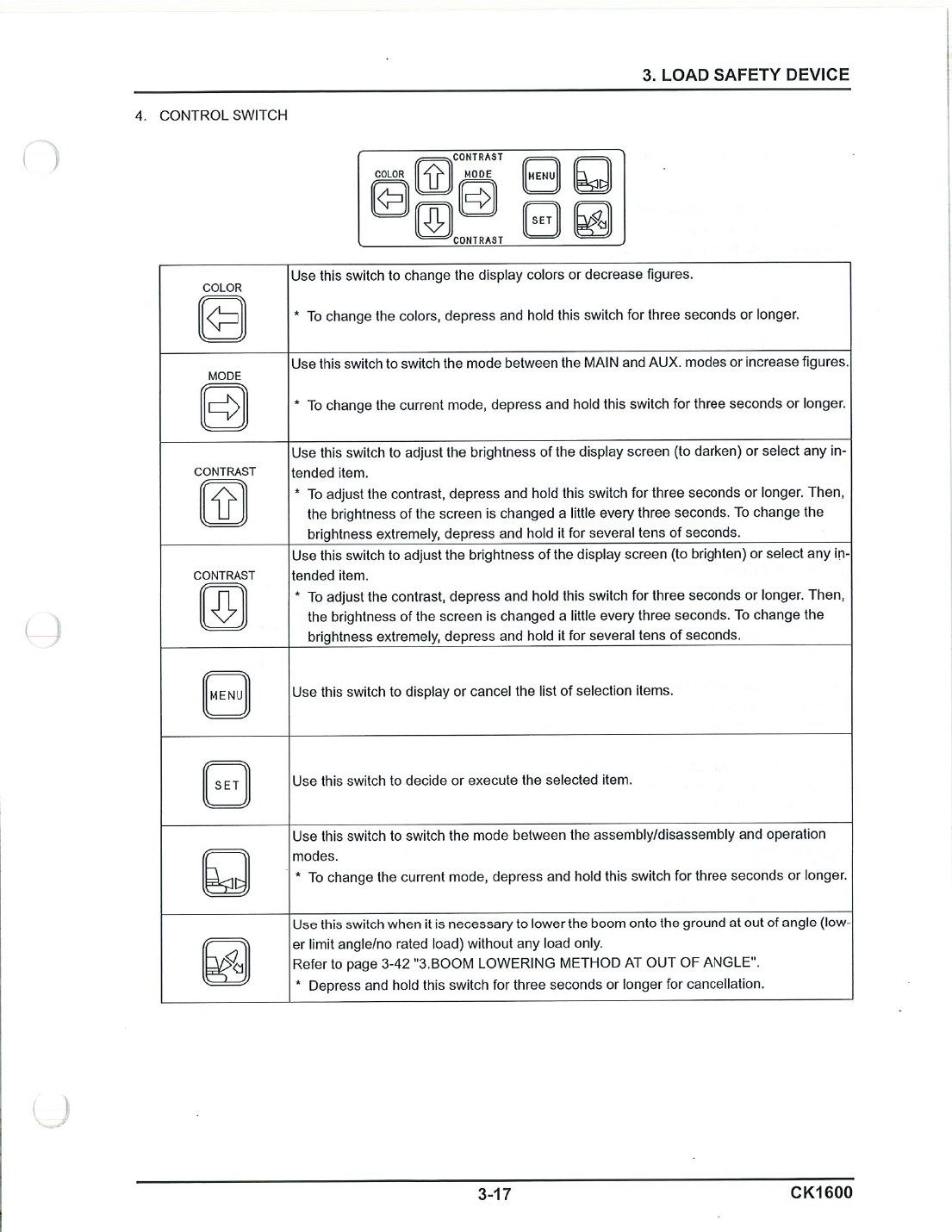
The installed controller layout distinguishes display, audible warnings, control switches, protected memory-card access, and adjustment switches. Source: CK1600 O&M PDF p102, LMI controller anatomyOpen the complete controlling page
Focus viewGeneral description and dimensions: type, maximum lifting capacity with the radius and boom it applies to, boom lengths and the machine dimensions, each printed with its unit.
The specification page consolidates machine geometry, working weights, ground bearing pressure, speeds, and power-system data; serial applicability remains unresolved. Source: Supplied CK1600 Spec Book PDF p2Open the complete controlling page
The test is specificity
"Check the hydraulic level" is generic crane theory. "Centre of the sight gauge, engine running, oil at 20 °C, gantry cylinder extended, crawler cylinder extended" is this machine. The second one is what gets assessed.
Ten knowledge-check questions at the end
All on the critical points of this module. It requires 100%, and the correct answer is not shown on a miss.
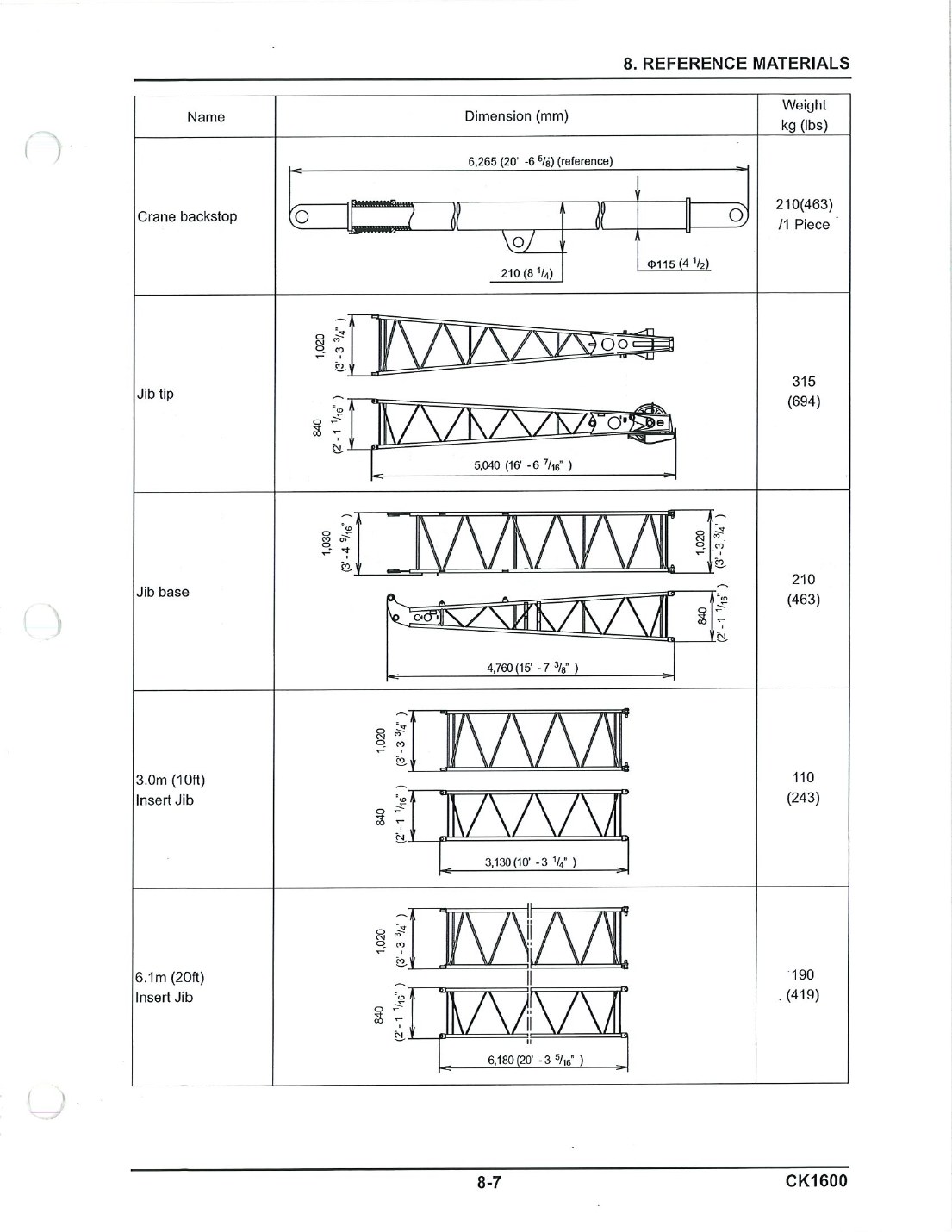
40, 60, 80 or 100 ft, at 10° or 30° offset. Built from a jib base with strut (2,270 lb), 10 ft (270 lb) and 20 ft (520 lb) inserts, and a jib tip (690 lb). Mounts only on booms of 90 ft through 200 ft.
Reference drawings give orientation, dimensions, and weights for backstops and the fixed-jib base, tip, and inserts. Source: CK1600 O&M PDF p338, backstop and jib-section referenceOpen the complete controlling page
Auxiliary sheave
650 lb. Fits booms of 50 ft through 240 ft. Maximum 2 parts of 26 mm rope, so the most it can ever lift is 59,000 lb.
Both cost you capacity
Mount either one and main boom rated loads are reduced — 1,250 lb for the auxiliary sheave, 7,055 / 8,010 / 8,965 / 9,920 lb for a 40 / 60 / 80 / 100 ft jib. That deduction applies whether or not you are lifting on the jib.
Angle is sensed by the boom angle detector in the boom base and shown continuously on the LMI beside boom point elevation, radius, actual load and rated load. The angle field turns red when an overhoist limit switch trips, and the message window names which one.
Stop
Angle
LMI controller, crane mode
80.0 – 80.5°
Boom overhoist limit switch
82 ± 0.5°
LMI, self-removal mode
86°
Left backstop limit switch
about 90° — cannot be released
Over-lowering
varies with boom length
Backstops are telescopic with a spring bumper and are required for all boom lengths.
O&M PDF p92, p102, p136 · Spec Book PDF p5, p20Reference O&M p92
Attachment lubrication and the daily attachment check cover the same hardware — boom foot pin, boom point sheaves, idler sheave, auxiliary sheave, jib point sheaves, strut sheaves, upper and lower spreader sheaves, cable rollers, hook block sheaves and swivel, backstop pivot, and every pinned connection.
High-strength steel
The boom, jib, gantry, mast, backstops and struts are high-tension steel. Special repair procedures are required — a damaged or deformed boom is not a welding job for the yard, it is a call to an authorised KOBELCO distributor.
O&M PDF p266–268, p281Reference O&M p266
Swing: one bearing, three brakes' worth of control
A fully revolving upper on a single-row ball slewing bearing with an internal integral gear, driven by a hydraulic motor through a planetary reducer. 360° at 2.1 rpm.
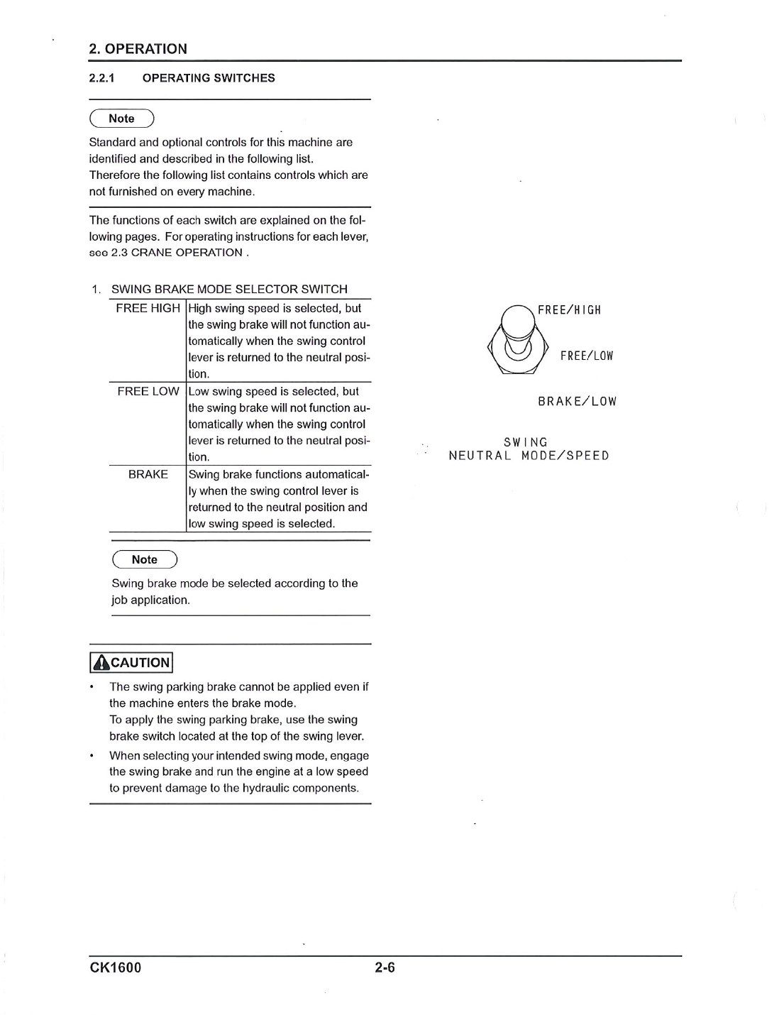
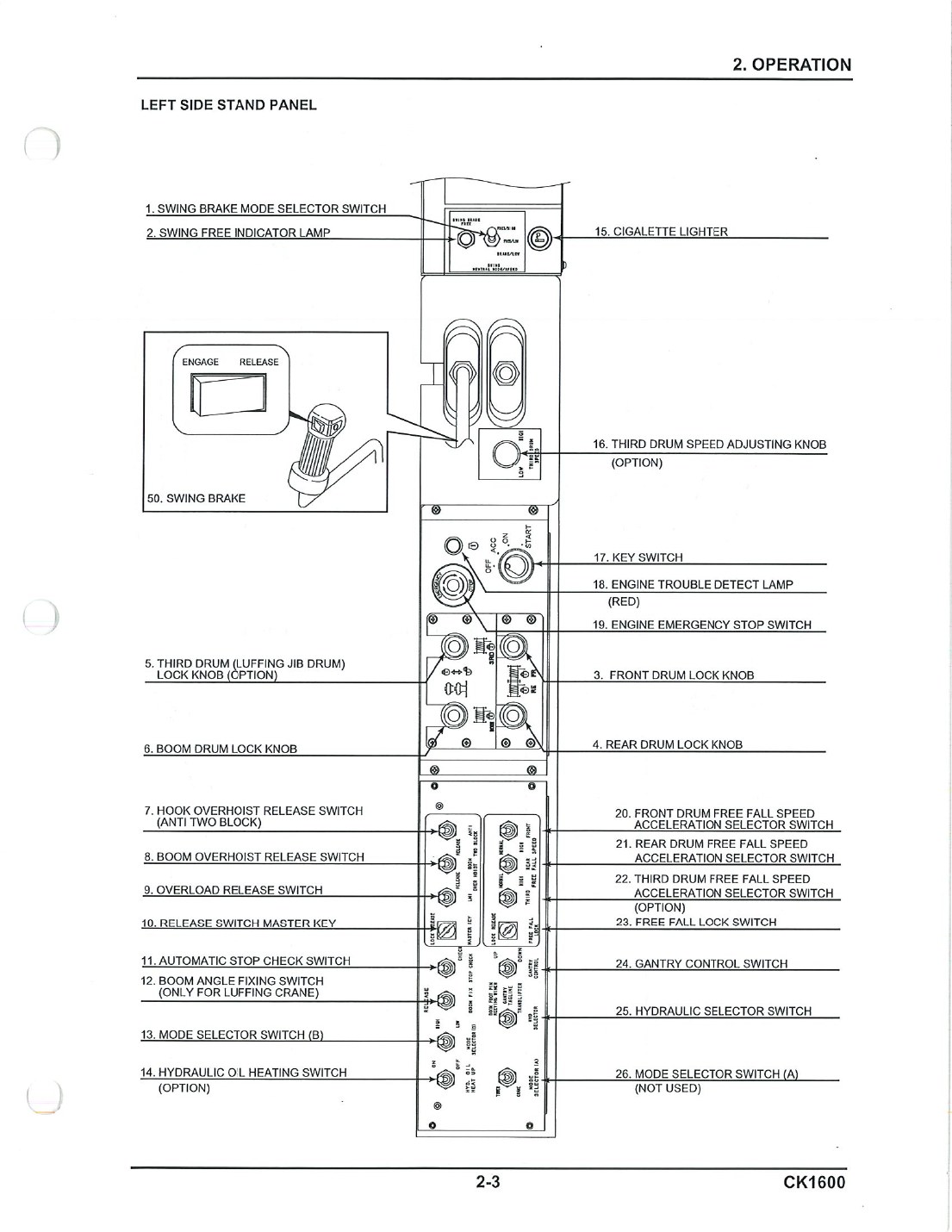
Focus viewSwing brake mode selector: in FREE HIGH and FREE LOW the swing brake does not apply when the lever returns to neutral; in BRAKE it does. The caution further down: the parking brake is the switch on top of the swing lever.
The three swing modes are defined by both speed selection and whether braking occurs when the lever returns to neutral. Source: CK1600 O&M PDF p39, swing brake mode selectorOpen the complete controlling page
Compare stopping, parking, and locking
These controls have different functions on this CK1600. The stability restriction below still applies.
Swing brake switch
Purpose: On top of the swing lever. ENGAGE / RELEASE. This is the one that applies the parking brake.
Mode selector
Purpose: FREE/HIGH, FREE/LOW, BRAKE/LOW. In BRAKE the swing brake applies automatically at neutral. It cannot apply the parking brake.
Swing lock
Purpose: A mechanical 4-position lock for transportation. Check daily that the pin inserts smoothly.
Spec Book PDF p4 · O&M PDF p39, p48, p142–144, p248
Swing is not always 360°
With 53 t of counterweight and no carbody weight the stability table forbids all-round swing — 240° available, 120° not. Firm ground only.
Spec Book PDF p4 · O&M PDF p39, p48, p142–144, p248Reference O&M p39
Every pump runs off one heavy-duty pump drive on the engine.
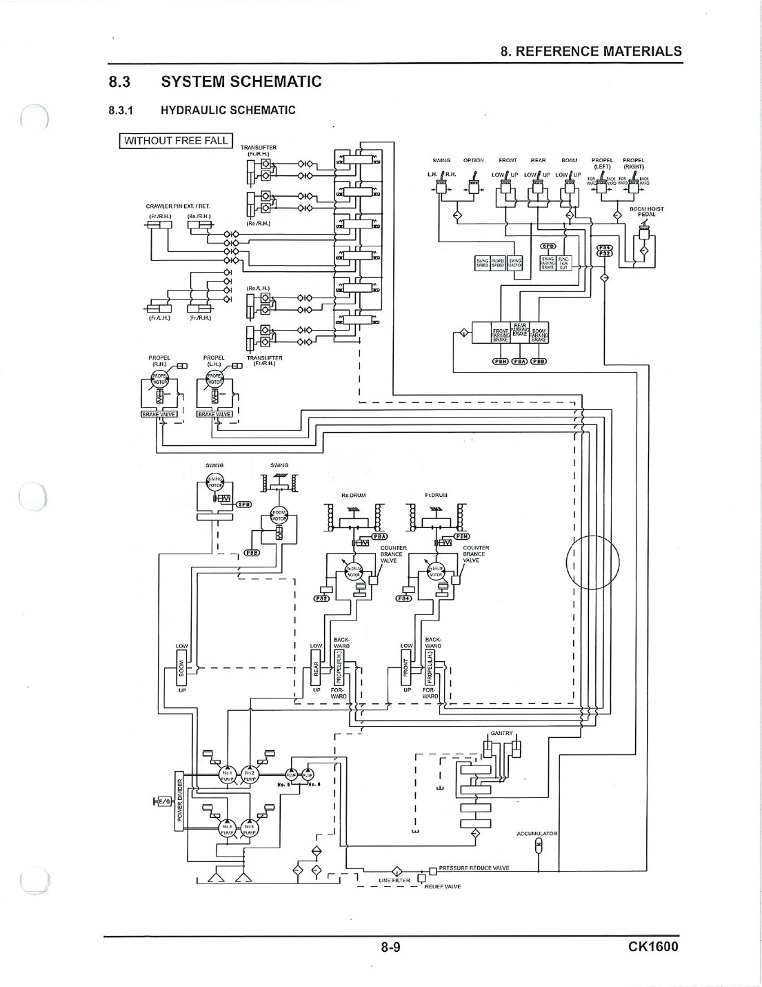
Focus viewAt the foot of the hydraulic schematic: the engine (E/G), the power divider and the numbered pumps it drives.
The hydraulic schematic is used for system orientation and troubleshooting boundaries, not as permission for operator-level repair. Source: CK1600 O&M PDF p340, hydraulic system schematicOpen the complete controlling page
Circuit
Pump
Load hoist and propel
2 piston pumps
Boom hoist
1 piston pump
Swing
1 piston pump
Control system and auxiliary
2 gear pumps
Brake cooling
2 gear pumps
The auxiliary circuit is switched by the hydraulic selector between boom foot pin / reeving winch, gantry / tagline / counterweight cylinder, and translifter. Two schematics are published — with free fall and without.
Spec Book PDF p3 · O&M PDF p340–342Reference O&M p340
Reservoir, fluid, and the level check that has four conditions
460 litres (121.5 gal), on the upper structure, with a sight level gauge, filler port, filter cover and drain plug.
Fluid
Hydraulic oil #46 — anti-wear, anti-oxidant, anti-foaming. KOBELCO KW46 general, KW32S cold region. By temperature the chart runs ISO VG68 / 46 / 32 / 22.
The level check is a posture, not a glance
Level is correct when it sits in the centre of the sight gauge with the engine running, oil at 20 °C, the gantry cylinder extended and the crawler extend/retract cylinder extended. Change any one of those and the reading is meaningless.
Before starting work, loosen the drain plug and drain water and sediment from the tank.
O&M PDF p274, p275, p293Reference O&M p274
Filters, and what a clogged one looks like from the seat
Cold-weather false alarm. W-15 can appear in cold weather with no clog at all. If the item disappears during warm-up, the cartridge does not need replacing.
Run at less than middle engine speed for 5 to 10 minutes with no load. Double that in a cold area. Working a cold machine wears the engine and the hydraulic components early, or damages them.
Cold free fall
A light load may lower slowly in free fall when cold. With the drum lock engaged, winch down for about five minutes to warm the oil.
Grade by temperature
ISO VG22 down to −25 °C, VG32, VG46, VG68 as it warms. Engine oil SAE 10W-30 covers 40 °C to −30 °C. Coolant runs to 50% antifreeze at −40 °C.
Focus viewThe operator's daily check: leaks, gauges after starting, controls, and the load brakes, tested by lifting a load a few inches off the ground and holding it.
The manufacturer checklist ties the pre-start inspection to logs, safety devices, load-bearing parts, leaks, gauges, controls, brakes, and clutches. Source: CK1600 O&M PDF p17, Operator's Check ListOpen the complete controlling page
Yours
Daily: hoses, piping and connectors for damage and leaks; hydraulic oil level; drain water and sediment before starting. Monthly: look over pumps, motors, reduction units and valves for leaks and unusual noise.
Not yours
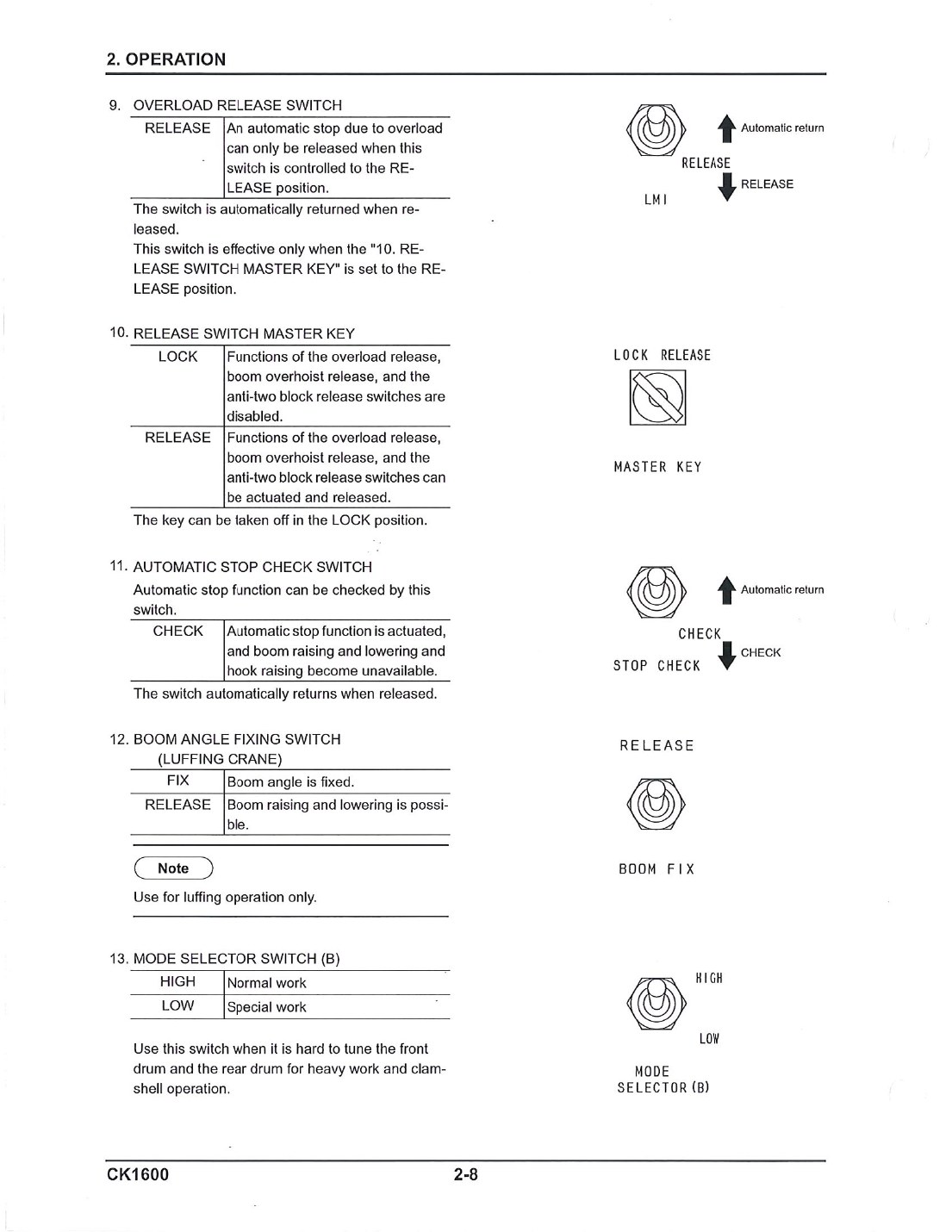
Relief settings, holding valves, brake feel changes, the LMI setting and adjusting switches. All distributor work.
Drift — an open item on this machine
Counterbalance valves hold the drums and boom hoist; parking brakes hold propel. Neither document publishes a numeric drift tolerance, and Kobelco may not have one. The operator-level check is the manual's: lift a load a few inches and hold it. Until your employer sets a hold time and an allowable movement, "a bit of settle" is an opinion rather than a test.
O&M PDF p17, p24, p246, p260, p340Reference O&M p17
Locate the indication before interpreting it. The OEM figure and labels remain available in full.
Enlarge numbered diagram
Scroll across the enlarged source image to read its labels and the added study numbers.
Locate the indication before interpreting it. The OEM figure and labels remain available in full. Numbered study labels have been added to the source image; they are separate from OEM numbering. Enlarge complete source page
What the source shows: The manual identifies the white area as normal and describes the response to a pointer in the red area.
Operator decision: Read the actual gauge and follow the complete response described in this lesson; a running engine alone does not prove normal condition.
Source PDF page(s): 49
2. Fuel gauge
Purpose: Indicates fuel level with a pointer.
What the source shows: The source labels F as full and E as empty.
Operator decision: Report the identified gauge and its reading; do not confuse it with coolant temperature.
Source PDF page(s): 49
3. Multi-display
Purpose: Displays the current status of the machine.
What the source shows: Status information appears in the liquid-crystal display below the two gauges.
Operator decision: Check for abnormal indications immediately after starting; the existing start-up fault response remains controlling.
Source PDF page(s): 49, 69
4. Display-screen selector switches
Purpose: Select the multi-display screens.
What the source shows: The OEM identifies the up/down triangle switches separately from setting and adjustment switches.
Operator decision: Identify the screen and control before using a reading; recognizing a screen is not authorization to change service settings.
Source PDF page(s): 49
CK1600 O&M PDF p49, gauge cluster configuration · CK1600 O&M PDF p49, with the lesson's existing p69 start-up response. This is the OEM layout, not a photograph of this crane.
Normal indications
Coolant gauge pointer in the white band. Engine speed shown in 20 rpm steps. In the red band: reduce engine speed and wait for it to return to white.
Check the monitor the moment it fires
Immediately after starting, check the monitor for abnormality. If the readings are improper, stop the engine at once and find the cause.
Spec Book PDF p2 · O&M PDF p49, p69, p332Reference O&M p49
All control levers neutral · function lock lever LOCK · swing brake switch engaging · all drum lock knobs LOCK · drum brake pedals lock position.
Start
Sound the horn. Key two steps right to ON — the warning lamp lighting is a bulb check. One more step to START, release as soon as it fires. Never crank more than 15 seconds; wait more than 20 seconds before retrying. Check the monitor immediately.
Stop
Same lever and switch settings as for starting, then idle about 5 minutes with no load, then key two steps left to OFF.
Specific gravity 1.25 to 1.27 at 20 °C is normal. Below 1.25, charge it. In extreme cold keep it above 1.22 — a fully charged battery resists freezing far better than a flat one.
Never
Never use the battery with electrolyte below the lower level — it degrades the battery and can make it explode. Never short across the terminals. Never fill above the upper level. Electrolyte is dilute sulphuric acid: eye protection, and flush with water on contact.
Isolation
Before any welding on the machine: stop the engine, key OFF, and disconnect the battery cable, to keep welding current out of the LMI controller.
O&M PDF p137, p313–314, p317–318Reference O&M p137
Use diesel ASTM 2-D only. This engine runs an electronically controlled high-pressure injection unit; substitute fuel damages the engine body and the injection unit, not just performance.
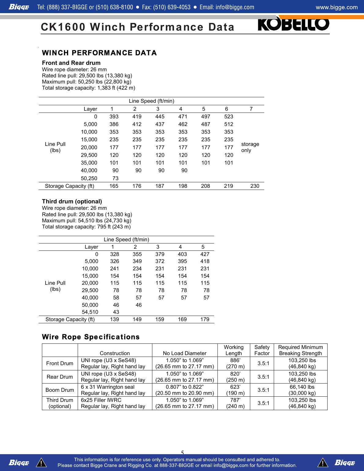
Winch performance and wire-rope tables tie drum layer, line pull, line speed, storage, construction, diameter, working length, and minimum breaking strength together. Source: Supplied CK1600 Spec Book PDF p6Open the complete controlling page
Design factor 3.5 : 1. Required minimum breaking strength 103,250 lb on the hoist lines, 66,140 lb on the boom hoist. Boom hoist is reeved 12 parts of 20 mm rope.
Diametral tolerance of KOBELCO standard rope is +2.5% to +4.5% of nominal. Rope outside that can upset on the drum.
Read each rope-table heading
Keep rope identity, a required minimum strength, and a hoist rating as separate source entries.
1. Identify the duty and construction
Read the correct drum row and the complete construction and lay description. Front, rear, boom, and optional third-drum entries are separate.
2. Read the diameter heading
The specification labels its column 'No Load Diameter'. Keep the heading and units with the entry instead of copying a bare number.
3. Keep strength and pull separate
The rope table states a required minimum breaking strength. Winch rated line pull is listed in the winch-performance section; they are different entries.
4. Retain the evidence boundary
Use the controlled equipment and rope records for the installed arrangement. The supplied specification alone does not resolve its applicability to this crane.
CK1600 Spec Book PDF p6, table headings.
Spec Book PDF p4, p5, p6 · O&M PDF p237, p269Reference O&M p237
The gauge cluster shows the current number of layers on the front drum and on the rear drum, changing as you winch.
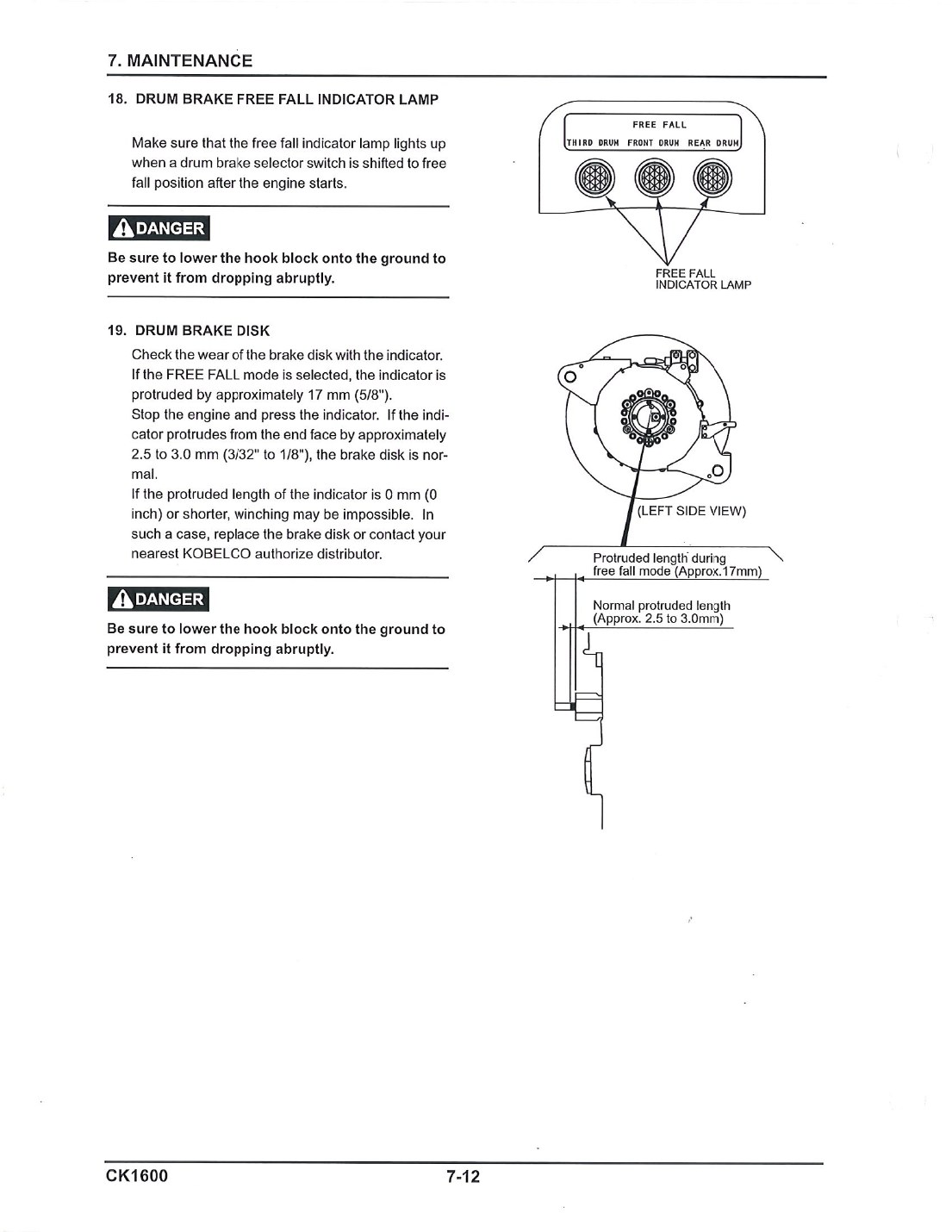
Brake disk wear indicator
In free-fall mode it protrudes about 17 mm. Engine stopped and the indicator pressed, 2.5 to 3.0 mm of protrusion is normal. 0 mm means winching may be impossible — replace the disk. Land the hook block first so it cannot drop.
Also fitted
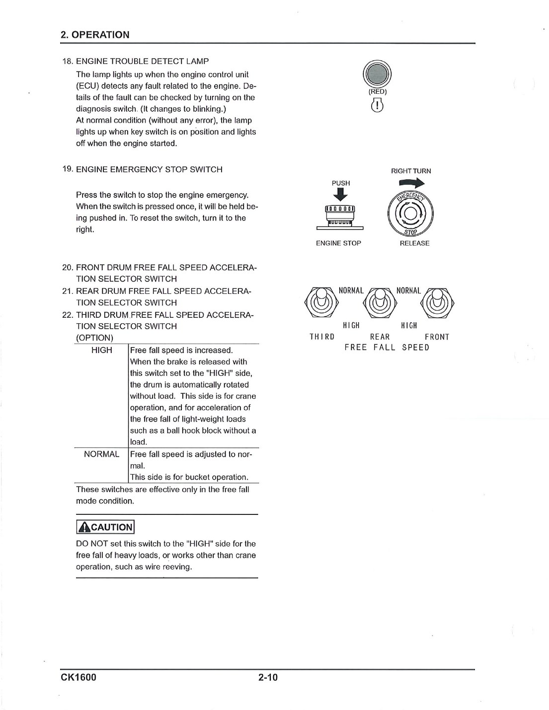
Free-fall indicator lamps per drum · drum turn grip selector (option) whose grip centre turns with drum speed · lifting height gauge (option).
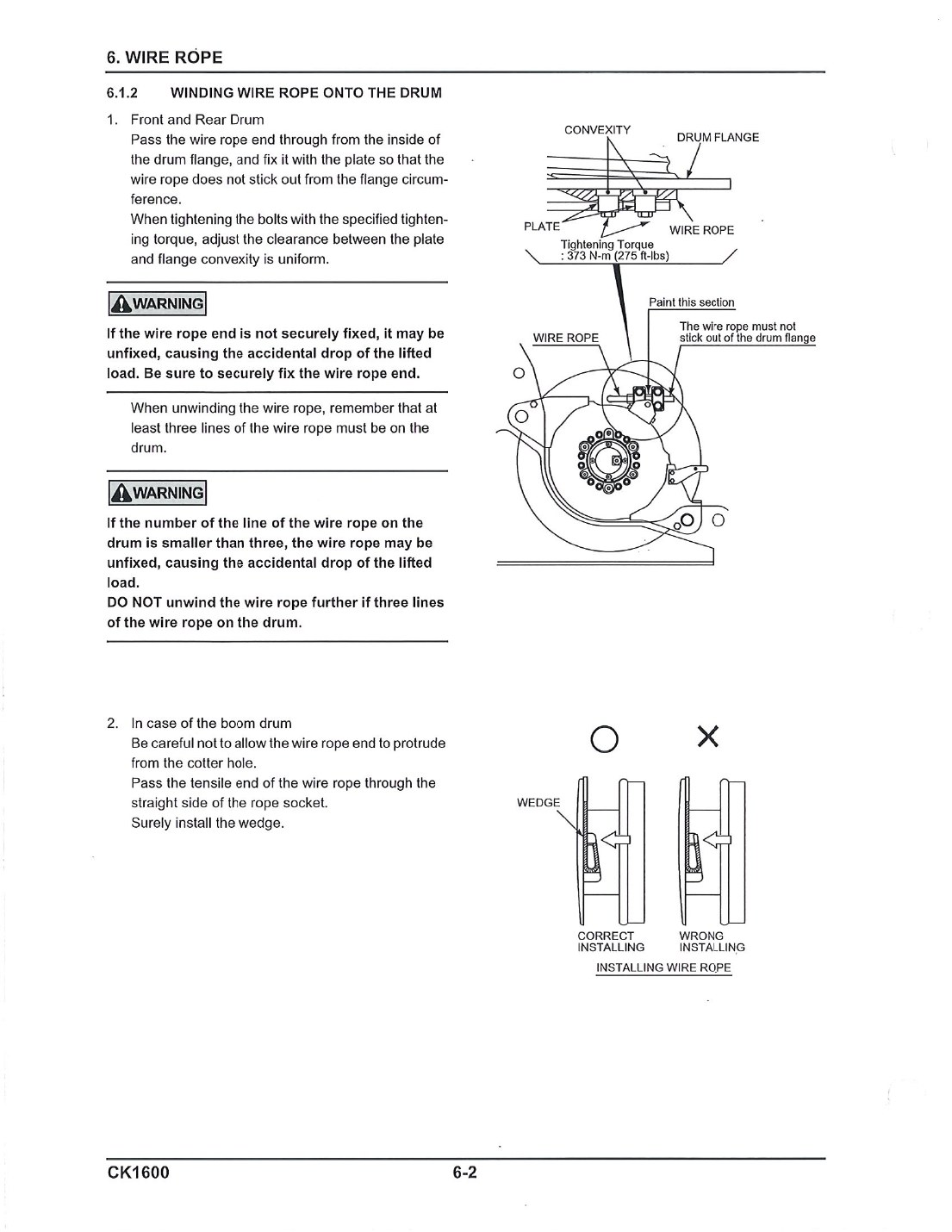
Beyond ordinary wear, the manual names conditions that retire a rope on sight:
Focus viewTwo warnings: a rope end that is not securely fixed, or fewer than three lines of rope on the drum, can drop the lifted load.
The maintenance diagram shows the drum-flange attachment, correct wedge orientation, and the tighter three-line minimum at the drum. Source: CK1600 O&M PDF p235, winding wire rope onto the drumOpen the complete controlling page
Kink · excessive deformation or corrosion · excessive elongation from overload or coming off a sheave · an electrical short circuit through the rope · exposure to fire, welding spark or high temperature.
Handling
Unreel without kinking. Wind on with light taps and steady tension so it beds tightly. Never handle rope with bare hands — gloves.
Guy line is different
The boom guy line fatigues and corrodes from the inside, so appearance cannot judge it. Replace on time: 2 years magnet or clamshell work, 4 mixed or frequent crane work, 6 normal crane work.
A walkaround that ends in a shrug is not an inspection. It ends in one of two words: serviceable, or out of service. Everything in this module builds toward being able to say the second one and make it stick.
The routine is already written
You are not inventing an inspection. Kobelco published three tables — upper, lower, attachment — plus an operator's check list. Your job is to run them in a repeatable order and know what each item is looking for.
Ten knowledge-check questions
All on the critical points of this module. 100%, no partial credit, correct answer not shown on a miss.
Focus viewUse the OEM sequence: records, safety devices, load-bearing parts, leaks, gauges, controls, brakes, and clutches.
The manufacturer checklist ties the pre-start inspection to logs, safety devices, load-bearing parts, leaks, gauges, controls, brakes, and clutches. Source: CK1600 O&M PDF p17, Operator's Check ListOpen the complete controlling page
The first item is not on the machine
The operator's check list opens by requiring you to check the machine log book — confirm periodic maintenance and inspections have been performed and all necessary repairs made. It is the most-skipped line on the list, and it is line one.
Every fluid check on this machine has a condition attached. Read it in the wrong state and the number is fiction.
Hydraulic oil
Centre of the sight gauge, engine running, oil at 20 °C, gantry cylinder extended, crawler extend/retract cylinder extended. Before starting work, loosen the drain plug and drain water and sediment.
The rest
Engine oil and the oil-change interval counter · radiator coolant level (W-6 if low) · fuel (W-11) · fuel pre-filter water, weekly · fuel filter water (G-25) · battery electrolyte level and specific gravity.
O&M PDF p274, p293, p54–56, p314Reference O&M p274
Wait until the machine has stopped. Never jump on or off. Use both hands and make sure of your footing.
Before climbing for maintenance
Make certain guards and walkways are clean and dry, and use a life belt. The deck decal warns that walking on guards causes stumbling on projected items and slipping on oil or water.
On the daily list
Item 16 — window glass, steps, handles and guards: cracks, damage, falling off. Keep them clean and remove grease and oil immediately.
Track tension is set by shim packs at the idler, not by a grease cylinder.
Recognize the method; respect the work boundary
The manual's service method is to travel forward about one crawler length so slack shows on top, then use the prescribed jack/adapter and move shims between packs (A) and (B), equalising both sides. This is recognition content for inspection and technician handoff. Perform the adjustment only when the employer assigns and authorizes it, the published procedure and correct equipment are available, and the machine is placed in the required maintenance-safe condition.
Why it matters both ways
Too tight — shoes wear quickly and a connection between two shoes can break. Too loose — the shoes can ride off the drive sprocket and idler during travel.
Daily lower check: crawler shoe for extension, damage and wear. Quarterly: drive sprocket, idler, upper and lower rollers, and the slewing ring bearing mounting bolts.
An inspection done from the seat, or from the side you parked on, is not an inspection of the machine. Half the daily items — crawler shoes, rollers, the far-side hoses, the far boom chord — are on the side you did not walk.
Conditions that hide defects
Darkness, mud, snow, fresh paint, and grease over a crack. The manual is blunt about the visual ones: dirty windows, darkness, bright sunlight, fog and rain make it hard to see — and if you cannot see clearly enough to operate safely, do not operate.
Daily on the attachment: boom point sheave, idler sheave, auxiliary sheave, jib point sheave, strut sheave — damage, deformation, wear. Plus the cable rollers on the insert and upper boom, and the sheave, bearing and wire lock of the hook block.
Check the sheave and frame of the upper and lower spreaders too — they carry the boom hoist reeving, 12 parts of 20 mm rope.
Wear gloves. Never run a bare hand along wire rope — a protruding broken wire will find it.
O&M PDF p266–267Reference O&M p266
Hooks: what the manual gives you, and what it does not
Hook condition changes daily with use, so hooks are inspected at the start of every shift and watched during operation. Remove affected equipment from service and have defects corrected by authorized personnel before using the block or ball.
Published criteria
Clean it. Lubricate the sheaves, swivel and every grease point. Check for wear and deformation, that the hook is not twisted, for the hook opening up, and for cracks. Check the rope at the dead-end socket for wear and broken wires, the socket for cracks, and the clips tight.
The latch
Every hook must have a latch and the latch must work. It must not be wired open or removed. It retains slings under slack conditions — it is not an anti-fouling device and must never support any part of the load.
Yearly, and never
Crack-test every hook and shackle at least yearly — dye penetrant, magnetic particle, ultrasonic or X-ray. Never repair a crack in a hook or shackle by welding.
Check on your crane
"Opening up" is only testable against a baseline, and neither CK1600 document publishes a throat dimension — throat dimensions belong to the hook maker, not the crane maker. ASME B30.10-2014 uses a 5% increase, never more than 1/4 in. (6 mm), unless the manufacturer says otherwise; it does not support the previously noted 15%. Identify the hook maker, measure each baseline, and have the employer confirm the applicable criterion before this becomes a scored check.
O&M PDF p272–273 · ASME B30.10-2014 §10-1.10.5Reference O&M p272
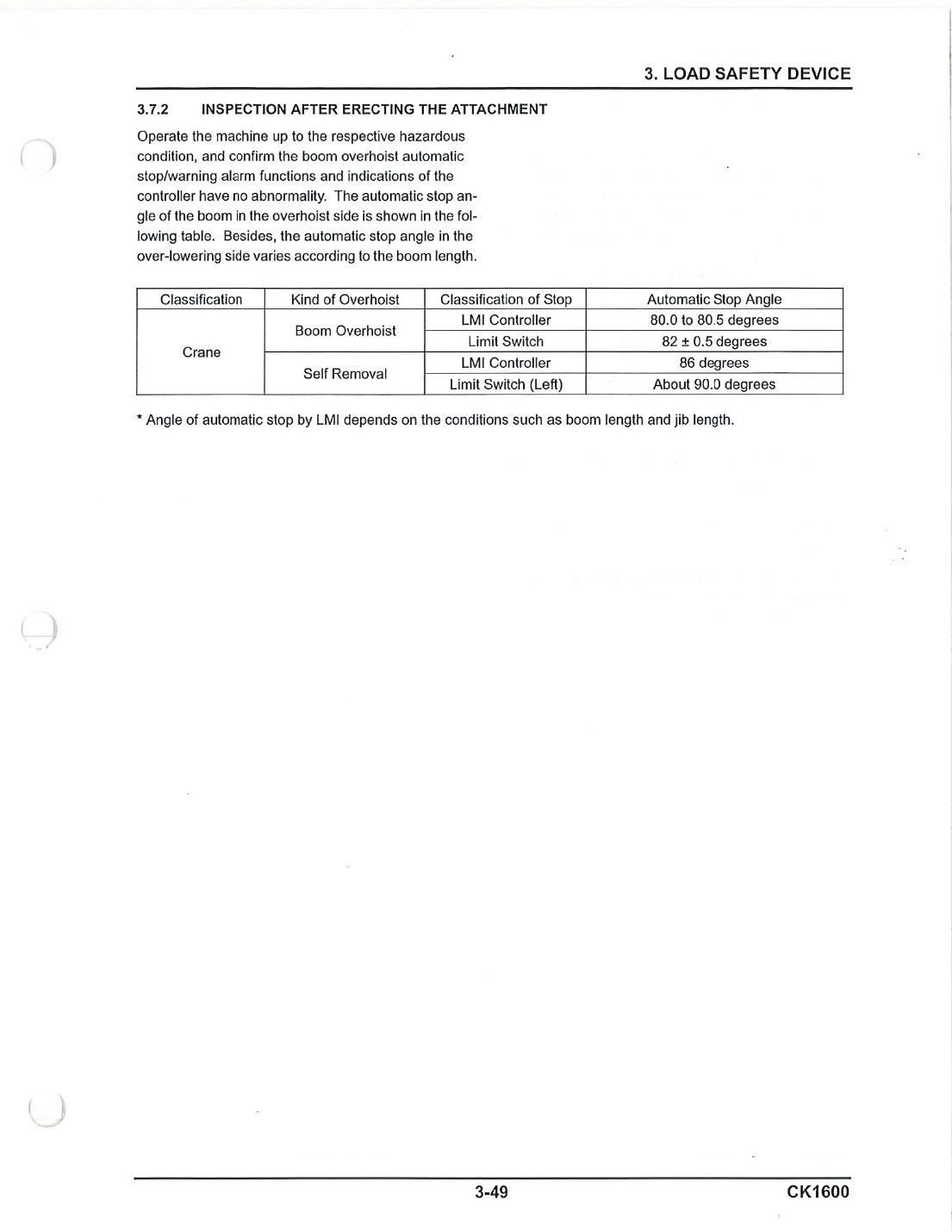
Swing brake effectiveness · swing lock pin · control lever play · drum lock knobs · hook overhoist device · boom overhoist device · load safety device — confirm operation is automatically stopped · indicator lamps · and the load brakes, by lifting a load a few inches and holding it.
The post-erection inspection table distinguishes controller and physical-limit-switch stop angles for crane and self-removal modes. Source: CK1600 O&M PDF p136, post-erection automatic-stop inspectionOpen the complete controlling pageThe diagram makes the brake-disk indicator inspection observable by separating free-fall protrusion, pressed measurement, and the zero-length failure condition. Source: CK1600 O&M PDF p251, free-fall brake disk indicatorOpen the complete controlling page
At assembly, before the boom goes up
Pull each limit switch once to a safe condition. Push the boom overhoist limit switch roller by hand and confirm the angle turns red with message (21) or (60). Push up the weight rope on each hook overhoist switch and confirm (17) or (18) appears and clears when pulled. Prove the overload stop with LMI CHECK MODE — the device simulates overload, message (56), and hoisting and boom lowering must both become impossible.
The manual's energy-isolation practice, assembled from where it states it:
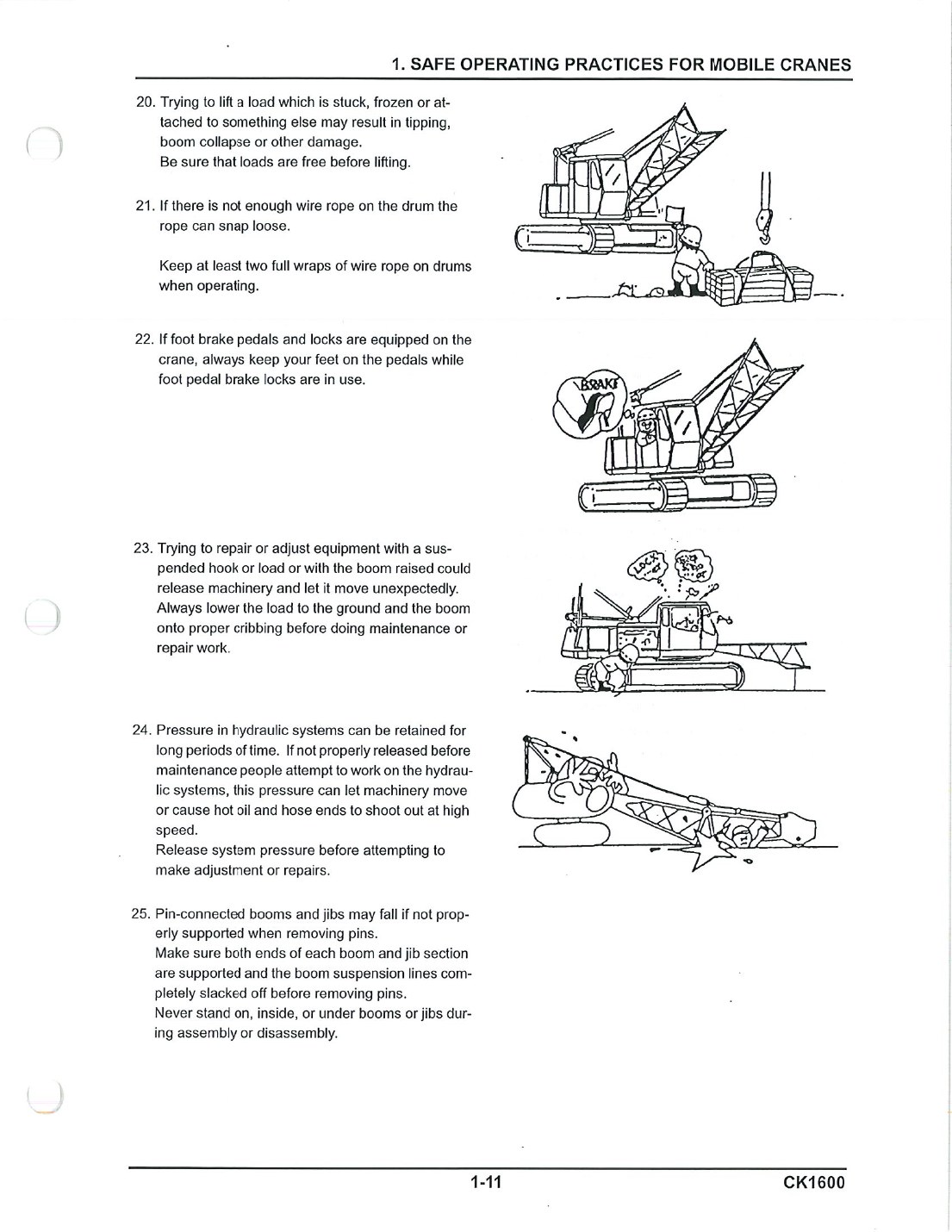
Lower the load to the ground and the boom onto proper cribbing before maintenance or repair. Trying to work with a suspended hook or a raised boom can release machinery unexpectedly.
Release system pressure before any adjustment — hydraulic systems retain pressure for long periods and can move machinery or send hot oil and hose ends out at speed.
Stop the engine, key OFF, function lock lever LOCK, drum locks engaged, swing brake set. For lightning, also turn off the load safety device power and the main switch.
Before any welding: engine stopped, key OFF, battery cable disconnected. Open the engine cover only with the engine stopped.
O&M PDF p24, p30, p71, p137, p242Reference O&M p24
A crane that is over its chart usually gets an alarm. A crane on ground that will not hold it gets no warning at all — the first indication is the machine moving.
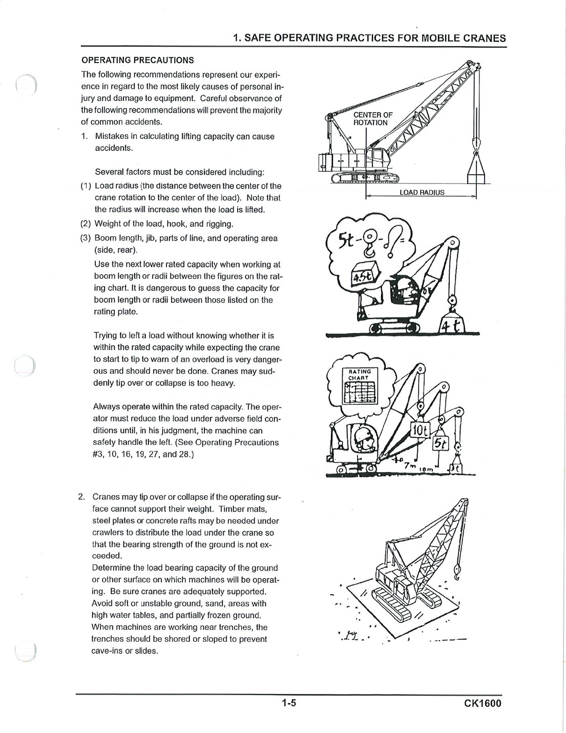
Focus viewFocus on the crawler support diagram and the ground-capacity warning beside it.
The manual illustrates load radius from the center of rotation and connects capacity work to ground support. Source: CK1600 O&M PDF p18, Operating PrecautionsOpen the complete controlling page
Two numbers, one comparison
What the machine imposes, against what the surface can carry. Everything in this module is in service of making that comparison honestly.
This area resolved clean
Everything in this module is answered by this machine's own documents. There is no excuse here that the manual did not say.
A crawler has no outrigger floats. It bears through two tracks, and the manual expresses that as a ground bearing pressure, not a point reaction.
Light counterweight
Standard counterweight
Working weight
273,000 lb
306,000 lb
Average ground pressure
10.5 psi
11.7 psi
Gradeability
30%
30%
Read the small print
Both figures include the base machine, a 50 ft boom and the hook block, with no load on the hook. They are averages over both tracks. The moment you pick a load, the real pressure under the loaded end of a track is higher than either number — and the manual does not publish how much higher.
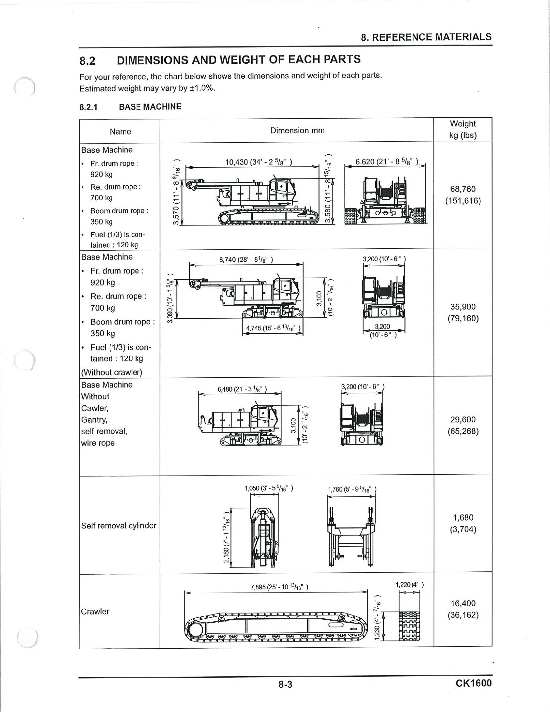
The tracks are 7,895 mm long overall but only 6,890 mm bears — the distance between tumbler centres. Size mats to the bearing length, not to what you can see.
O&M PDF p332 (8.1.2 Outside dimensions)Reference O&M p332
Soft or unstable ground · sand · areas with high water tables · partially frozen ground. Where the machine works near trenches, the trenches must be shored or sloped to prevent cave-ins or slides.
And the fix it names
Timber mats, steel plates or concrete rafts under the crawlers, to distribute the load so the bearing strength of the ground is not exceeded.
The table assumes something
The 4.1 swing and travel stability table is written for firm ground. On weak ground the manual's instruction is to cure the ground first and then operate with care — not to operate carefully on bad ground.
Timber mats, steel plates or concrete rafts may be needed to distribute the load so the ground's bearing strength is not exceeded. Determine the surface's capacity first, and be sure the crane is adequately supported.
Under the translifter
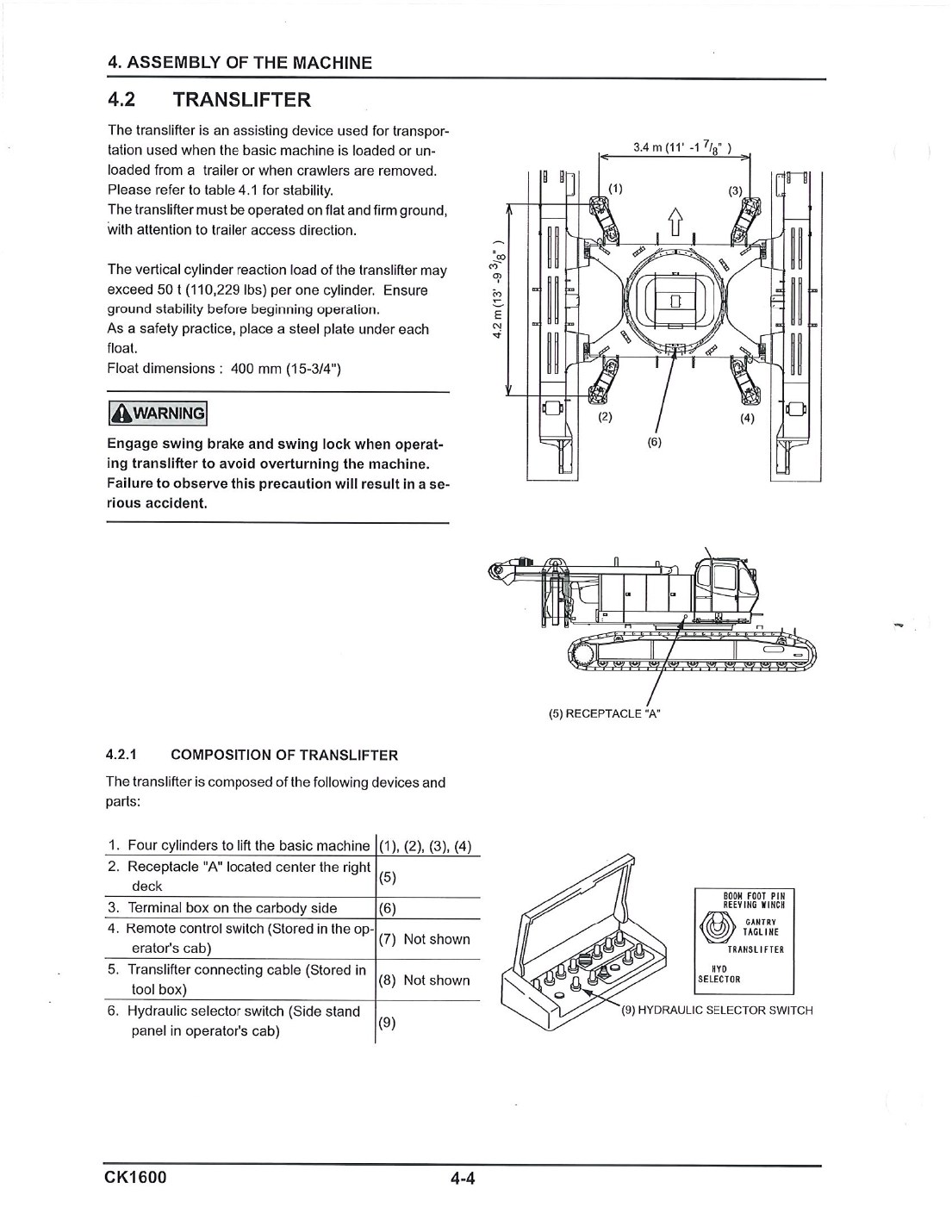
Operate on flat, firm ground. As a safety practice place a steel plate under each float — the vertical cylinder reaction may exceed 50 t (110,229 lb) per cylinder, through a float only 400 mm across.
That translifter figure is worth holding onto: four points, each capable of more than 50 tonnes, on 400 mm floats. It is the highest concentrated bearing pressure this machine ever produces, and it happens during assembly rather than during a lift.
Extracted in this manual from ASME/ANSI B30.5. Operation near energized lines:
Normal voltage, phase to phase
Minimum clearance
to 50 kV
3.05 m (10 ft)
over 50 to 200 kV
4.60 m (15 ft)
over 200 to 350 kV
6.10 m (20 ft)
over 350 to 500 kV
7.62 m (25 ft)
over 500 to 750 kV
10.67 m (35 ft)
over 750 to 1000 kV
13.72 m (45 ft)
In transit, no load, boom or mast lowered: 1.22 m (4 ft) to 0.75 kV · 1.83 m (6 ft) to 50 kV · 3.05 m (10 ft) to 345 kV · 4.87 m (16 ft) to 750 kV · 6.10 m (20 ft) to 1000 kV.
And the floor is not the ceiling
OSHA requires at least 10 ft from lines at 50,000 V or less, greater clearances above that, and some states require more. Where the voltage is not known, it is not 50 kV until somebody proves it — treat it as the highest credible value.
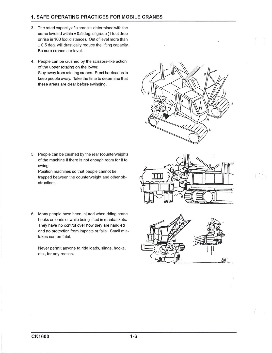
The manual sets the level requirement and illustrates rotating-structure and counterweight crush zones. Source: CK1600 O&M PDF p19, level and swing hazardsOpen the complete controlling page
The scissor
People are crushed by the scissors-like action of the upper rotating on the lower, and by the counterweight when there is not enough room for it to swing. Erect barricades, and take the time to confirm the area is clear before swinging.
Before the machine is committed to a setup spot, the operator needs to know all of this — and the manual's operating precautions assume every one of them:
The lift
Load weight including hook, block and rigging · load radius, and the fact that radius increases when the load is lifted · boom length, jib, parts of line · which quadrant the pick is in.
The ground
Bearing capacity · what is buried · what has been backfilled · what mats are available and what they are rated for.
The hazards
Power lines and their voltage · the swing and tail-swing path · adjacent structures and equipment · access and egress routes that must stay clear, including for emergency vehicles.
An operator reads the chart correctly, does the arithmetic correctly, and still puts the machine over — because the chart described a configuration the machine was not in.
A crawler has no detent
An outrigger machine gives you a pinned position you can see and a sensor that knows. This machine gives you neither. Every configuration fact here is established by looking, and by entering what you saw.
Crawler, not outriggers
Setup training for mobile cranes is dominated by outriggers, on-tires operation and jacking — none of which exist on this crawler. What replaces them is crawler and track configuration, the largest single topic in this module.
Rated capacity is determined with the crane levelled within ±0.5 degrees of grade — one foot of drop or rise in 100 feet. Out of level by more than that drastically reduces lifting capacity.
Focus viewThe rated condition begins with the crane level within the manual's stated tolerance.
The manual sets the level requirement and illustrates rotating-structure and counterweight crush zones. Source: CK1600 O&M PDF p19, level and swing hazardsOpen the complete controlling page
And the chart says it slightly differently
The chart's Supplemental Data requires the crane levelled to within 1%. One foot in a hundred is 1%, but ±0.5° is 0.87%. Work to the tighter figure.
No jacks, no adjustment
There are no jacks. This machine cannot correct level from the seat — level is established by preparing and grading the surface before the machine gets there, and lost level is a ground problem with a ground solution.
O&M PDF p19 · Spec Book PDF p20Reference O&M p19
How you confirm half a degree — and the carbody level to verify
The manual is silent; the OEM walkthrough points to the carbody
No level gauge, bubble level or levelness indicator is described anywhere in the serial-applicable manual — not in the control locations, gauge cluster or controller display. Kobelco's CK1600 Intro walkthrough says a level is mounted on the carbody as an aid. That narrows where to look on this crane; it does not prove the same device is still fitted or accurate. Photograph it if present and compare it with a calibrated external level.
Why a small angle is a big error at long boom
Out of level tilts the whole machine, so the boom tip moves sideways by an amount that grows in proportion to boom length. The same half a degree that is almost invisible on a 50 ft boom displaces the tip a long way on a 250 ft one — and that displacement is added radius, on a chart that assumed none. This is why the tolerance is stated as a grade rather than as a feel.
One position is not a check
A bubble read in a single boom position tells you about that position. A machine can sit level over one end of the tracks and be out of level over the side, because the support under a crawler is rarely uniform. Confirm in the quadrants you will actually work in.
It does not stay where you put it
Level is not established once. It is lost progressively, by settlement under load, and this machine has no jacks to correct it. So the interval at which level is re-checked has to be set deliberately — and a lift that loses level mid-pick is a ground problem with a ground solution, not something to trim out from the seat.
O&M PDF p19 (operating precautions 3) · control locations PDF p35–p48 · gauge cluster PDF p49–p53 · controller display PDF p102–p106 · OEM CK1600 Intro video, -e0FONywGGA, about 3:20 (carbody location)Reference O&M p19
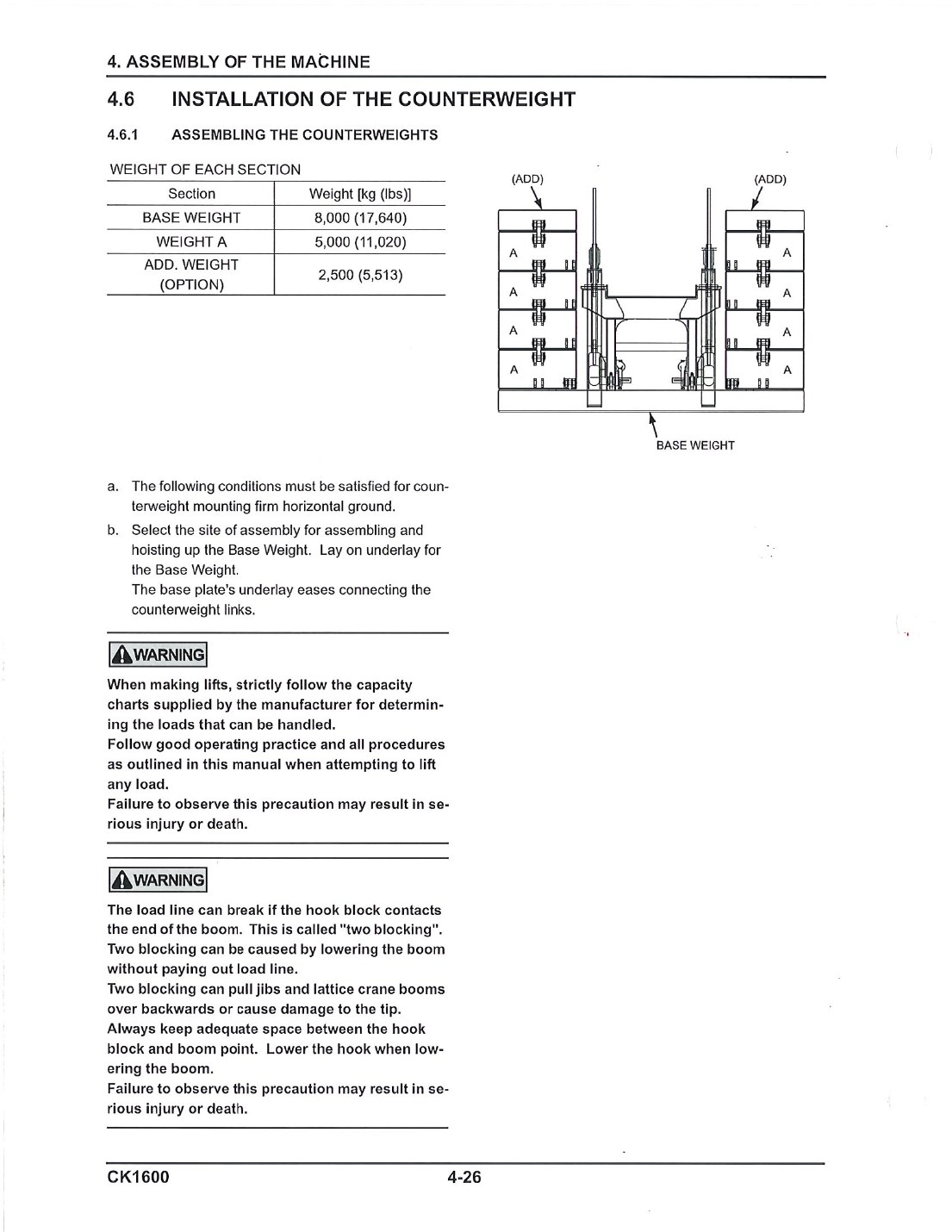
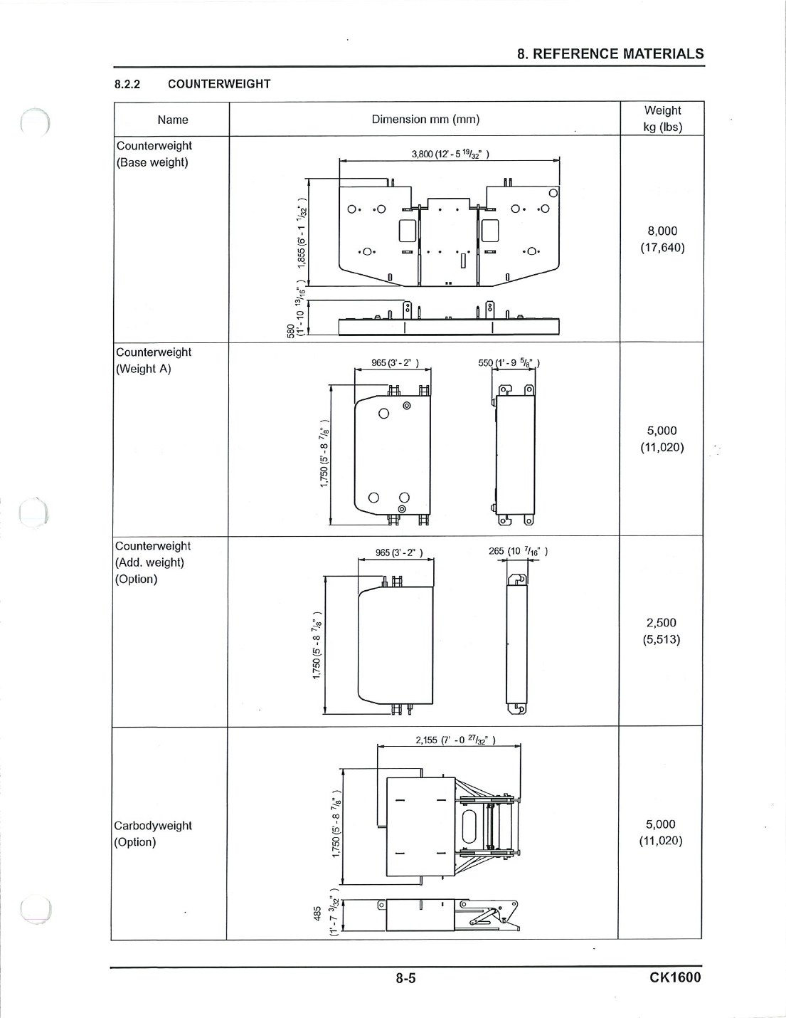
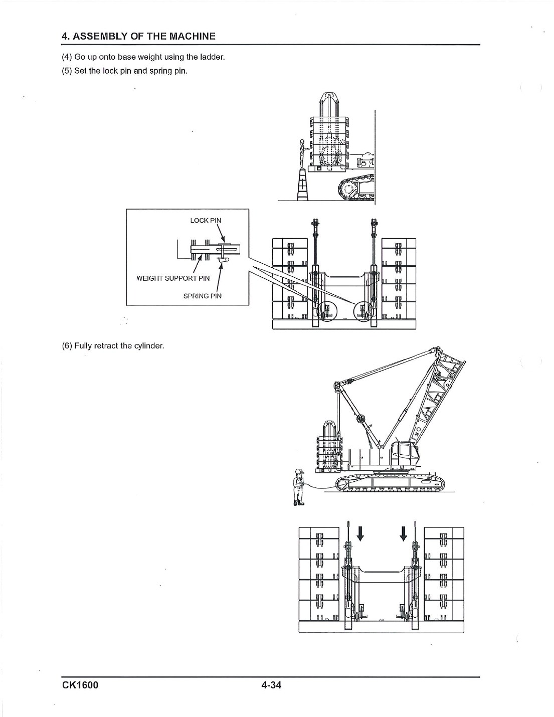
The manufacturer stack diagram and component weights establish which slabs belong in the counterweight assembly. Source: CK1600 O&M PDF p167, counterweight assemblyOpen the complete controlling pageBase weight, standard slabs, additional slabs, and carbody weights have different identities, dimensions, and individual weights. Source: CK1600 O&M PDF p336, counterweight dimensions and weightsOpen the complete controlling page
The one that matters most
Every rated load chart supplied for this machine is for the Standard arrangement. If this crane is worked light, not one capacity in the chart book applies to it — and there is no light-arrangement chart in the documents supplied.
Spec Book PDF p2, p3, p8, p9, p20
Fitting it, removing it, and the machine that does it to itself
This machine self-assembles and self-disassembles. That is a capability and a hazard, and both are documented.
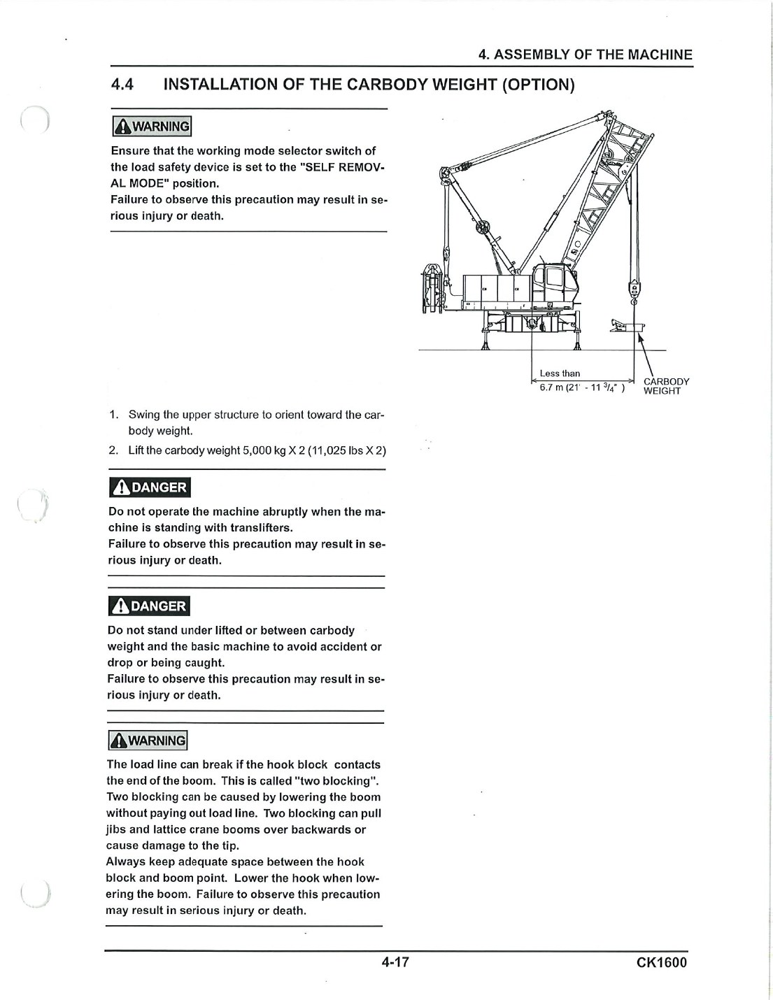
The carbody-weight installation page combines configuration, position, clearance, and line-of-fire warnings. Source: CK1600 O&M PDF p158, carbody-weight installationOpen the complete controlling page
Operation
Where it is written
Install counterweight
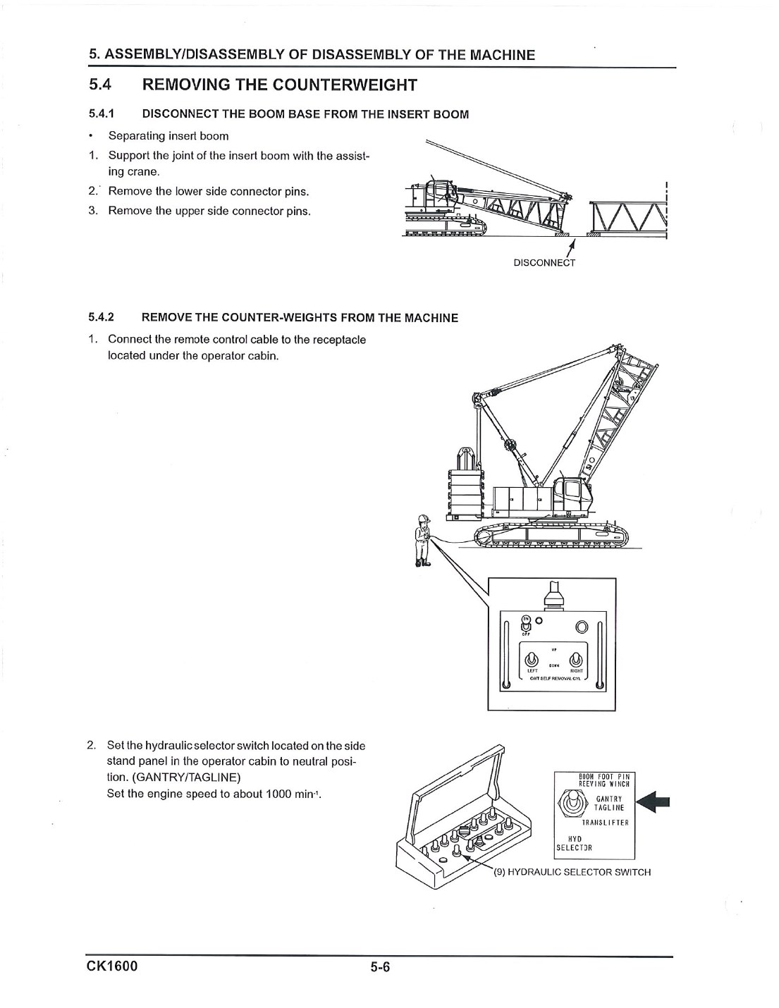
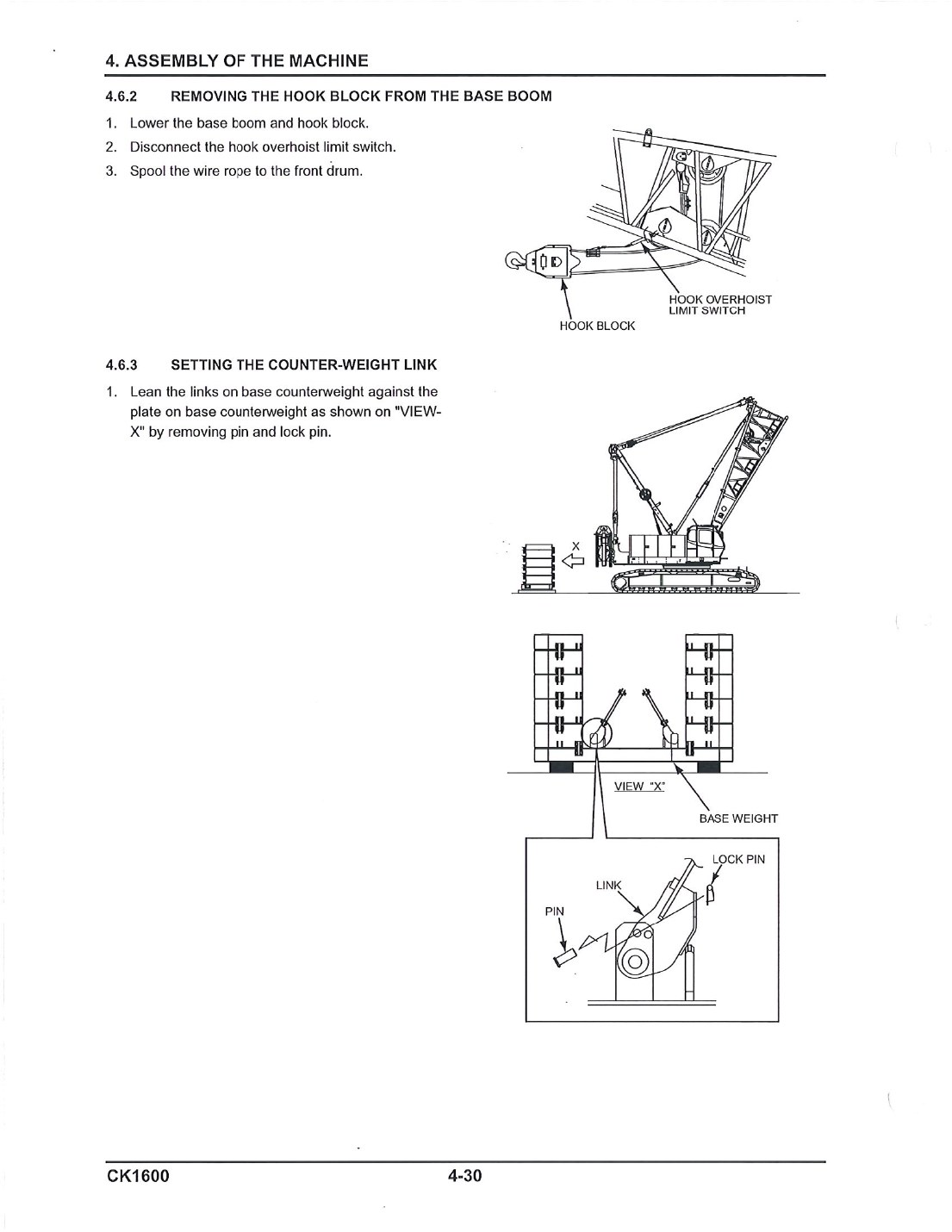
Assemble the counterweights · remove the hook block from the base boom · set the counterweight link · install counterweights to the machine
Install carbody weight
A separate procedure (option), and again in the initial assembly chapter
Remove counterweight
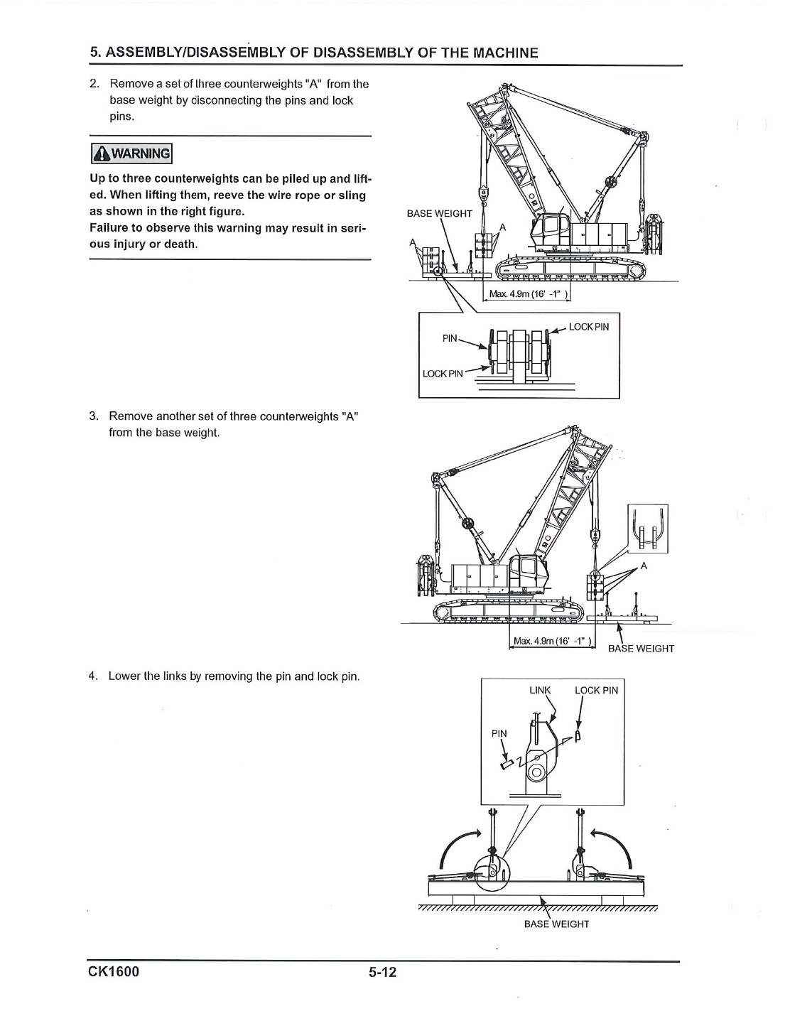
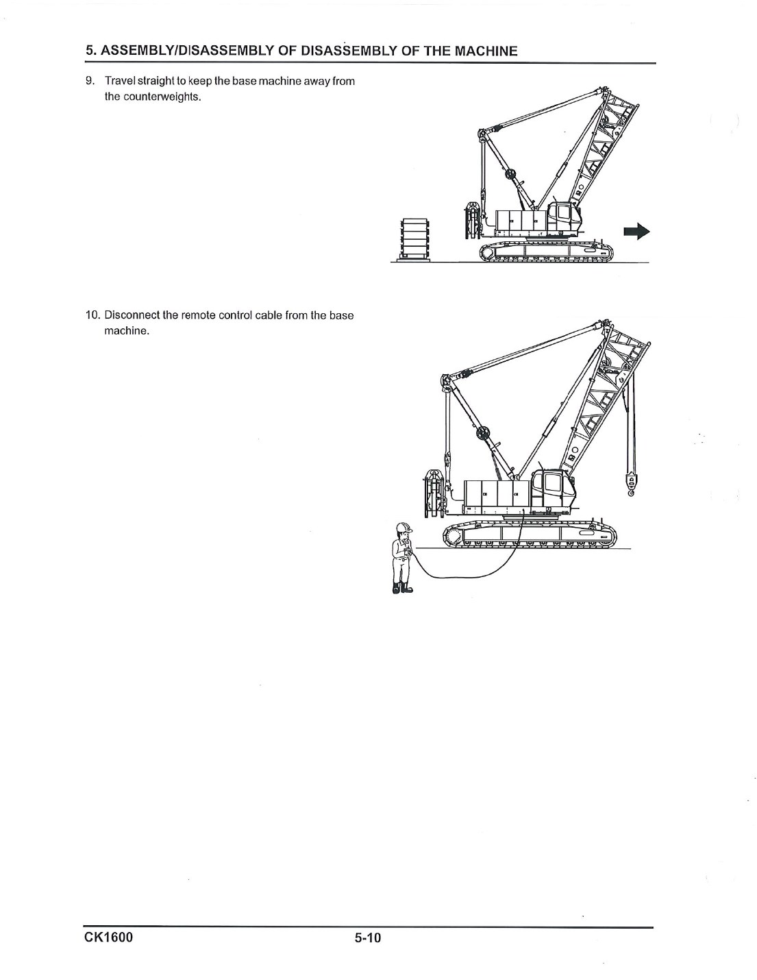
Disconnect the boom base from the insert boom · remove the counterweights · install the hook block to the boom base · disassemble the counterweight · then remove the carbody weights
Self-removal hardware
Counterweight self-removal device with a self-removal cylinder, fed through the hydraulic selector switch
Translifter
Four lifting cylinders, used to load and unload the base machine and to remove the crawlers
Gantry
Hydraulically erected. Must be fully raised for all operations
Two rules that are not negotiable
All counterweights must be removed before operating the translifter — that one carries its own decal on the machine. And the counterweight fitted changes what the machine is permitted to do at all: the stability tables gate all-round swing and each direction of propel on the counterweight and carbody weight combination.
Translifter ground
Flat, firm ground, and as a safety practice a steel plate under each of the four floats: the vertical cylinder reaction may exceed 50 t (110,229 lb) per cylinder, and the float is only 400 mm (15-3/4 in.). Four small feet carrying that is a ground-bearing problem, not a hydraulics problem.
Self-removal mode changes the protection
The controller has a dedicated self-removal mode in which the ordinary boom overhoist stop is not actuated and the left backstop limit switch takes over at about 90 degrees. Different mode, different protection — worth knowing which one the machine is in.
The check that catches the other crew
Field modification of counterweight, up or down, is on the daily check list as something to confirm has not happened. A configuration changed by another crew and not verified at shift start is the named failure in this Task.
O&M PDF p167–p176 (4.6 installation of the counterweight) · removal PDF p211–p217, p226 · translifter PDF p145 · self-removal PDF p126, p136, p232 · decal PDF p10 · field mod PDF p17Reference O&M p167
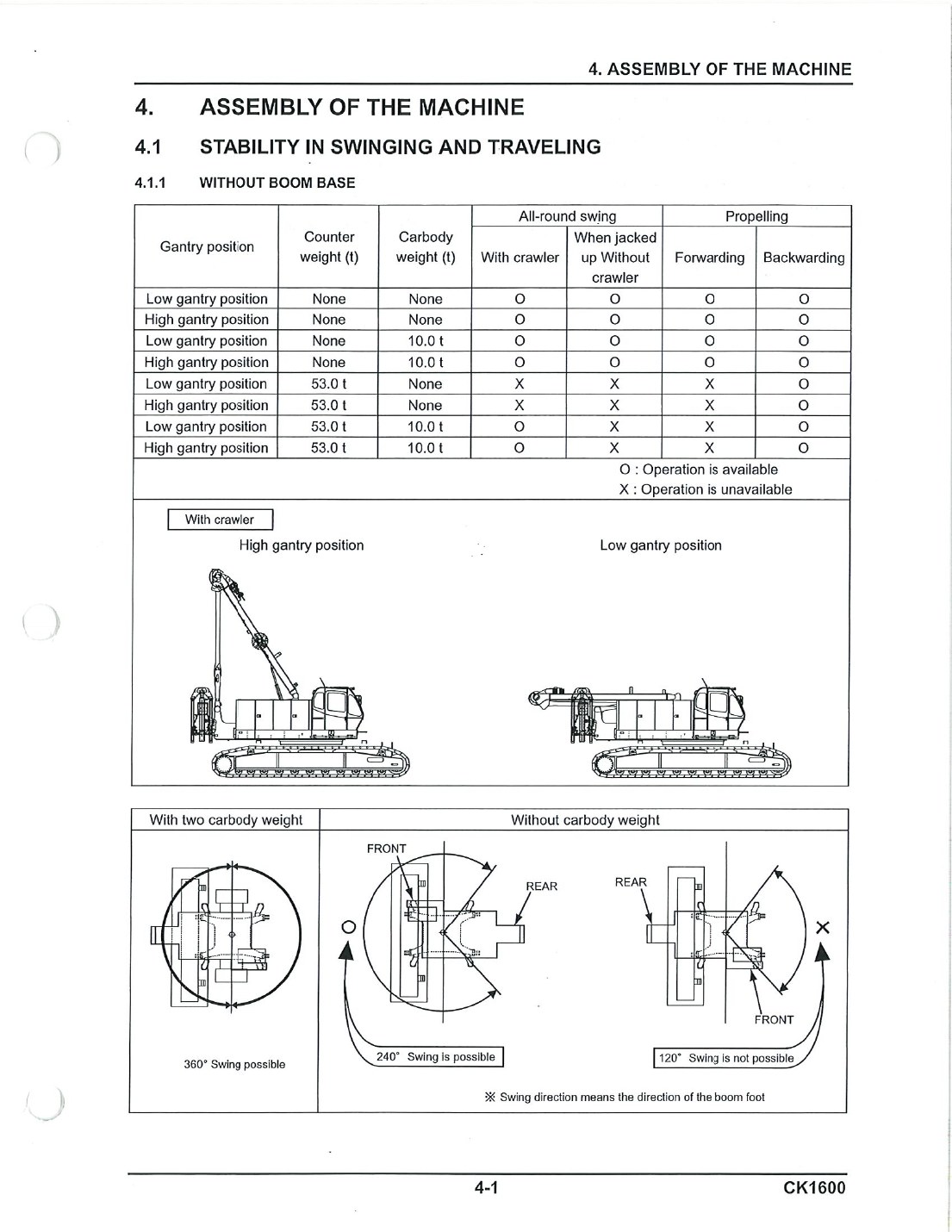
Section 4.1 answers, for each combination of gantry position, counterweight and carbody weight, whether all-round swing and each direction of travel are available at all.
Assembly movement and swing permissions change with crawler, gantry, counterweight, and carbody-weight state; the table, not habit, controls. Source: CK1600 O&M PDF p142, assembly stability tableOpen the complete controlling pageThe assembly section defines forward and backward travel by counterweight position and publishes the no-load slope condition. Source: CK1600 O&M PDF p143, travel direction and slopeOpen the complete controlling page
Configuration
All-round swing
Forward propel
Backward propel
No counterweight
available
available
available
53 t CW, no carbody weight
UNAVAILABLE
UNAVAILABLE
available
53 t CW + 10 t carbody weight
available
UNAVAILABLE
available
…with boom base fitted
available
max 3° angle
available
Direction has a meaning
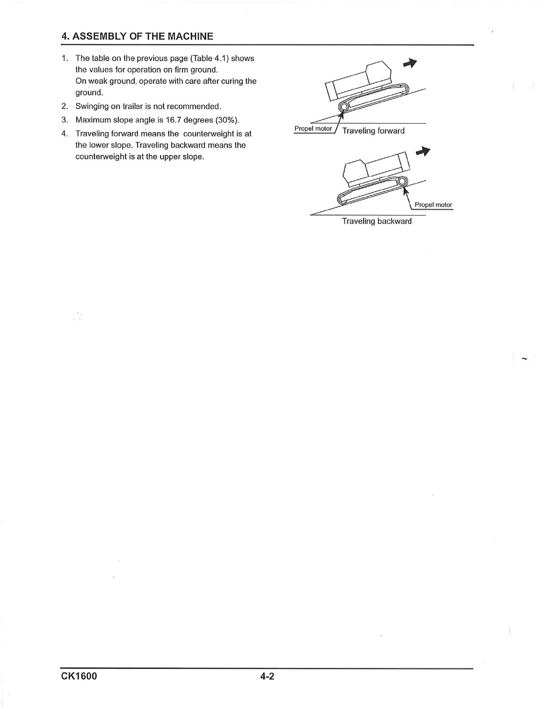
Travelling forward puts the counterweight at the lower side of the slope. Travelling backward puts it at the upper side. Maximum slope angle is 16.7° (30%).
Firm ground only
The table is written for firm ground. On weak ground, cure the ground first. Swinging on a trailer is not recommended.
6,890 mm — 22 ft 7-1/4 in., between tumbler centres
Average ground pressure
72.3 kPa — 10.5 psi, at working weight, no load
Track gauge, extended
6,620 mm — 21 ft 8-5/8 in.
The word average is doing a lot of work
10.5 psi is published as an average over both track bearing areas, at working weight with no load on the hook. What is not published is how pressure redistributes along a track under load, over the side, or with the boom over an end — which is precisely where a crawler concentrates its bearing. The published figure is a starting point for a conversation with an engineer, not a permission slip.
So the problem is worked from the ground
Determine the load-bearing capacity of the operating surface first. Use timber mats, steel plates or concrete rafts under the crawlers to distribute the load so the ground's bearing strength is not exceeded. Avoid soft or unstable ground, sand, high water tables and partially frozen ground. Shore or slope nearby trenches. The swing and travel stability table is valid for firm ground only — on weak ground, cure the ground first.
Uniform, continuous, both tracks
The bearing length is only a bearing length if it is all bearing. Support has to be uniform and continuous along the full length of both tracks. A soft spot, a void, or a buried obstruction under one end of one track is the worst case, because that is where load concentrates when the boom comes over that end — and unlike an outrigger at a pinned detent, a crawler on prepared ground gives you no positive indication that the setup is correct. Verification here has to be deliberate, every time.
O&M PDF p332 (8.1.2 outside dimensions) · PDF p18 (operating precautions 2) · firm ground PDF p143 · levelness PDF p19Reference O&M p332
Gauge, tension, and the quadrant the chart does not restrict
Overall crawler width 6,620 mm (21 ft 8-5/8 in.). This is the published working width, and the condition the hydraulic oil level check assumes — crawler extend/retract cylinder extended.
Retracted, transport
The position exists — there are extend/retract cylinders and a crawler pin extend/retract function on the selector. Neither the retracted gauge nor any chart governing lifting in the retracted position is published in this manual. Confirm on this unit and obtain the governing chart before any lift is planned with the crawlers retracted.
Why this matters
Operating or travelling with the track gauge in a position other than the one the chart in use assumes is a named failure — and here the retracted chart does not exist, so there is nothing to be in compliance with.
Track tension: both errors bite
Tension is set by shim packs at the idler. Too tight and the shoes wear quickly and a connection between two shoes can break. Too loose and the shoes can ride off the drive sprocket and idler during travel. The adjustment: travel forward about one crawler length so the slack appears on top, remove all shims from pack A, jack the idler wheel out until the slack is gone, move the shims into pack B and the remainder back into A, then equalise the tension right and left. Daily lower check covers the crawler shoe for extension, damage and wear; the sprocket, idler and rollers are on the quarterly check.
360 degrees is not the same as equal
Every chart for this machine is a 360 degree rating, so the chart itself restricts no quadrant. That is not the same as saying every direction is equal: the least stable position is over the side, the boom should be erected over the front of the crawlers rather than laterally, and at 240 ft boom or over blocks must be placed at the end of the crawlers when lifting from or lowering to the ground. Quadrant is referenced to the carbody, not to where the upper happens to be pointing.
O&M PDF p326 (7.10.4 crawler shoes adjustment) · PDF p332 · PDF p293 · checks PDF p260 · Spec Book PDF p20 (chart notes 10, 11)Reference O&M p326
Propelling with a load, once the table has allowed it
The stability table decides whether. These are the requirements for how, and they are separate from the table.
Before and during travel
Before moving
Confirm people and obstacles are clear, sound the horn, and use a signal person
Be especially careful when
The boom is long · the boom angle is large · the ground is uneven · a load is lifted
Inputs
Do not start or stop travel or steering abruptly. Rapid starts and stops side load the boom
Hoisting during propel
Extreme care is required when hoisting or lowering a load while propelling
Radius
The radius will increase when the load is lifted
Grade
Maximum slope angle 16.7 degrees (30 percent). Forward puts the counterweight at the lower side; backward puts it at the upper side. With the boom base fitted and 53.0 t counterweight plus 10.0 t carbody weight, forward propel is limited to a maximum 3 degrees
Ground
Firm ground only — the table is written for it. On weak ground, cure the ground first
The swing you must not chase
A load that starts swinging during travel is being fed by the machine's own motion. The instinctive correction — steering or accelerating to get under it — adds input in phase with the swing and makes it worse. Slow, straight, and let it settle.
And the speed you have
Travel speed is 1.3 / 0.9 km/h (0.81 / 0.6 mph), high and low, selected on the propel speed selector. In HIGH, pivot turn and counter rotation may not be possible depending on ground conditions and engine speed — which is a reason to be in LOW on the ground where you would want a pivot turn.
O&M PDF p142–p144 (4.1 stability in swinging and traveling) · propel cautions PDF p72–p73 · radius growth and side load PDF p18, p23 · speed PDF p332Reference O&M p142
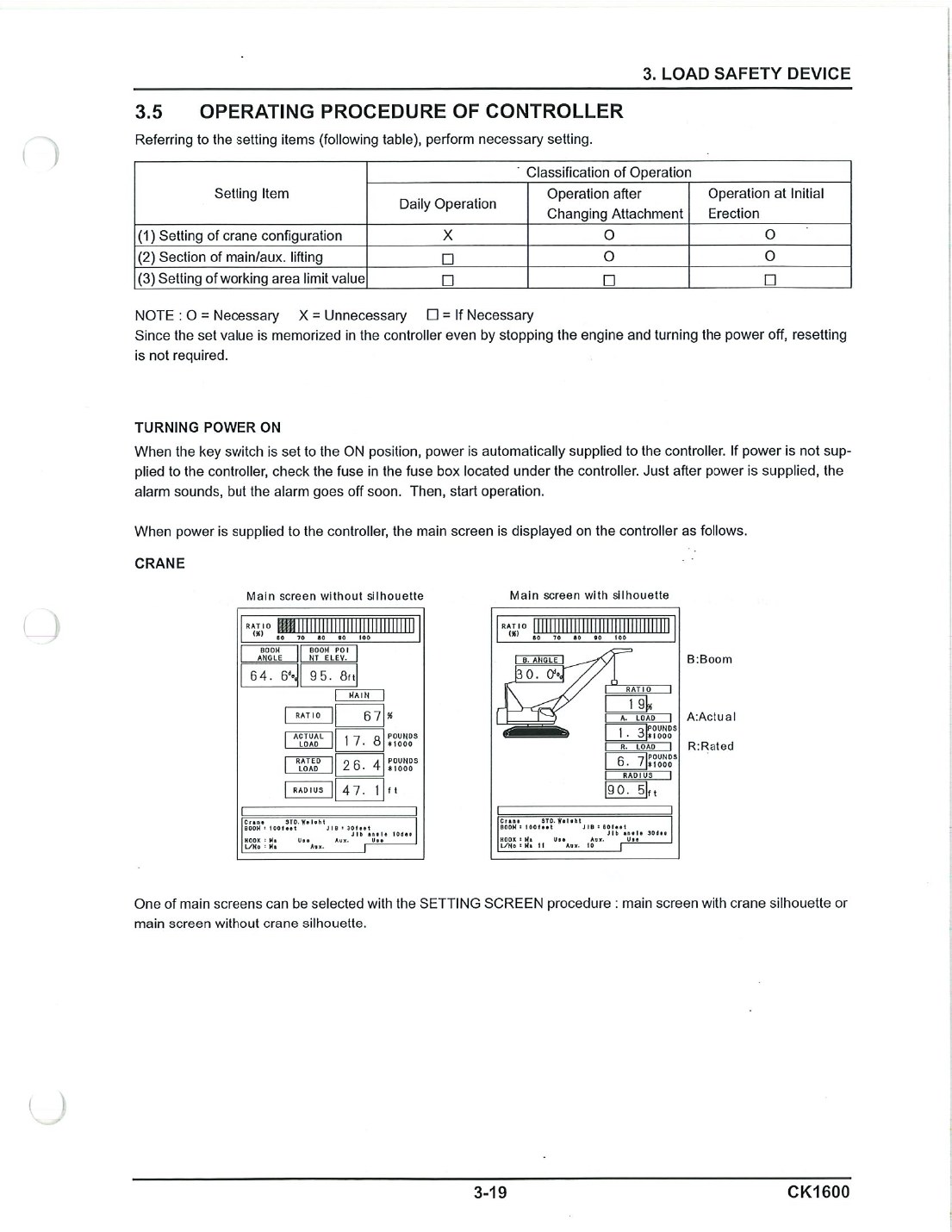
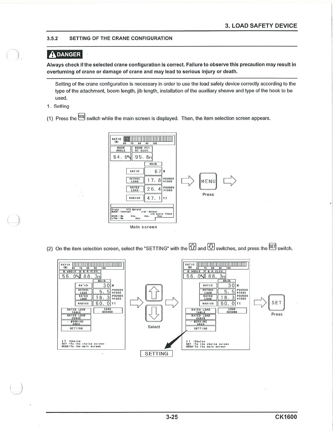
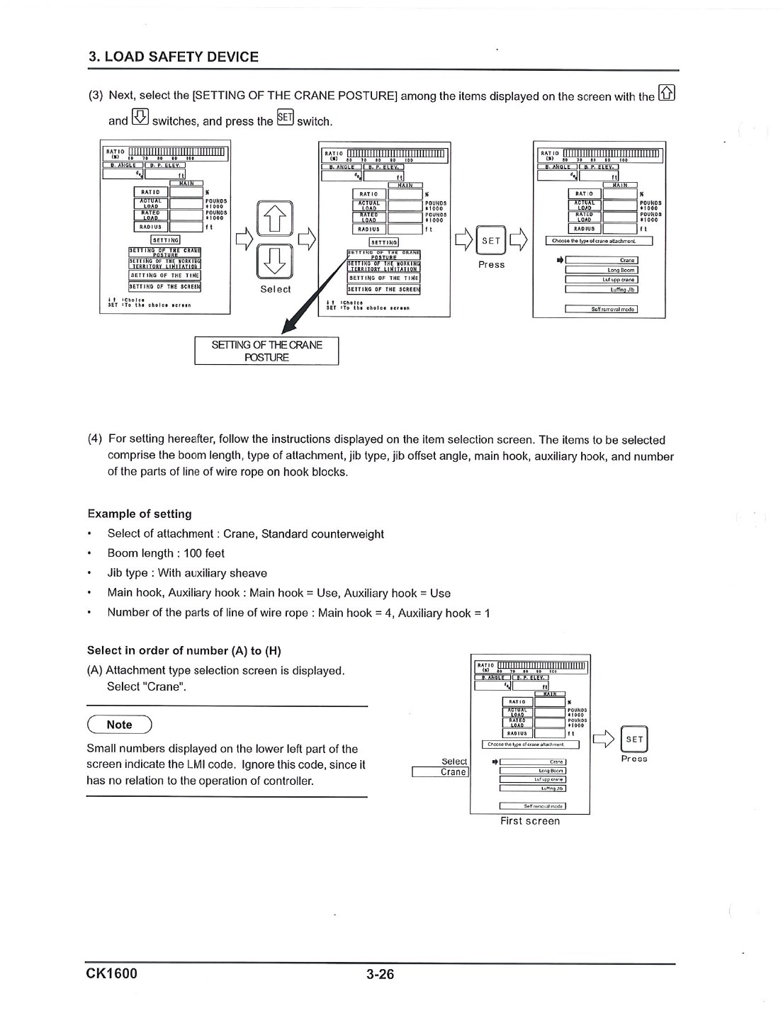
Setting the crane configuration is required after changing the attachment and at initial erection. The manual's standing instruction: always check that the selected configuration is correct — a wrong one can overturn or damage the crane.
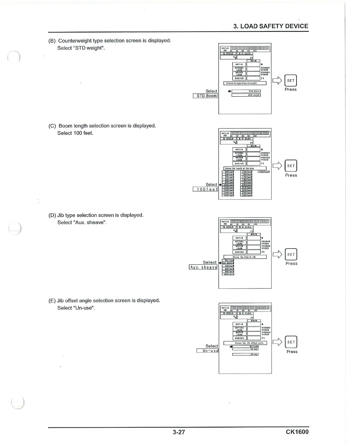
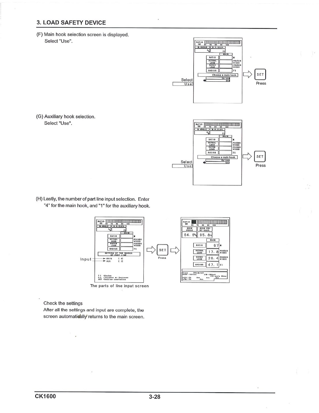
The operating procedure distinguishes initial erection, attachment changes, and daily operation before showing the normal main-screen indications. Source: CK1600 O&M PDF p106, LMI operating procedure and main screenOpen the complete controlling pageConfiguration setting begins from the main screen and carries an explicit warning to verify that the selected configuration is correct. Source: CK1600 O&M PDF p112, configuration-setting entryOpen the complete controlling pageThe manual names the attachment, boom, jib, hook, and parts-of-line selections that must describe the physical crane. Source: CK1600 O&M PDF p113, configuration parametersOpen the complete controlling pageThe setting sequence requires deliberate selection of counterweight type, boom length, jib type, and jib offset. Source: CK1600 O&M PDF p114, counterweight, boom, and jib selectionOpen the complete controlling pageMain hook, auxiliary hook, and the parts of line for each are the final configuration inputs before the operator checks the displayed setup. Source: CK1600 O&M PDF p115, hook and parts-of-line selectionOpen the complete controlling page
Step
Selection
A
Attachment type — Crane / Jib / Self removal
B
Counterweight type
C
Boom length in feet
D
Jib type — none, auxiliary sheave, or jib
E
Jib offset angle
F
Main hook — Use / No use
G
Auxiliary hook — Use / No use
H
Parts of line, main and auxiliary separately
They persist
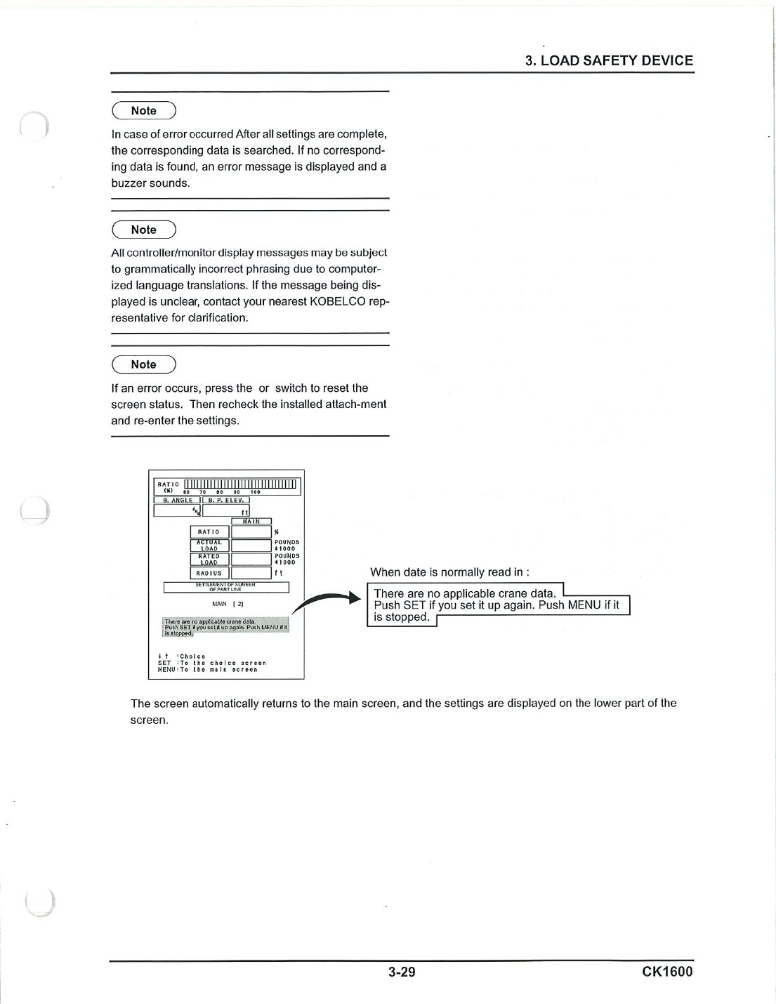
Settings are memorised in the controller through engine stop and power off. They will happily describe the previous crew's machine, with confident numbers on the display.
Alarms
90% — yellow, intermittent buzzer, intervals shortening as ratio rises. 100% — red, continuous buzzer, automatic stop. Working-area limits warn 5° or 1 ft before the stop, or at 90% of a set load.
Review each configuration category
Settings persist after power-off; use the complete OEM setting procedure and verify the actual machine.
1. Selection A
Attachment type — Crane / Jib / Self removal
2. Selection B
Counterweight type
3. Selection C
Boom length in feet
4. Selection D
Jib type — none, auxiliary sheave, or jib
5. Selection E
Jib offset angle
6. Selection F
Main hook — Use / No use
7. Selection G
Auxiliary hook — Use / No use
8. Selection H
Parts of line, main and auxiliary separately
O&M PDF p103, p112–116, p118, p124
O&M PDF p103, p112–116, p118, p124Reference O&M p103
The configuration entry is only worth the protection it buys — and there is a defined list of things that protection does not extend to.
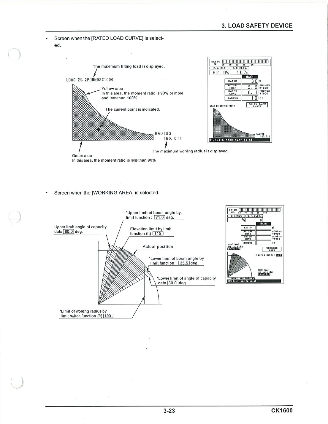
The controller visualizes capacity ratio and configured work-area limits; neither display substitutes for verifying conditions the system cannot sense. Source: CK1600 O&M PDF p110, rated-load curve and working areaOpen the complete controlling page
Not protected against
Why the system misses it
Side load
It computes a moment from load and radius. A line off plumb puts bending into the boom that no load pin reports
Dynamic load
It reads what the pin sees now. Acceleration, deceleration and shock arrive and pass; the structure feels them whether or not a stop trips
Ground failure
Nothing measures the surface. A track settling changes level and radius while every displayed number still looks correct
Rigging failure
The system's world ends at the load pin. Slings, shackles and below-hook devices are outside it entirely
Out of level
There is no documented level input to the controller. The OEM walkthrough's carbody-mounted level, if fitted and accurate on this crane, is a local visual aid — it does not make the LMI compensate for out-of-level radius error
Operating to the alarm
The pre-alarm at 90 percent is a warning, not a working condition. Normalising it — running to the beep because the beep has not stopped anything yet — spends the one margin the stability-limited rows actually have, and on a structural row there is no lean or lightening to notice at all.
The override, narrowly
Three spring-returned release switches under a master key, each releasing one stop, each annunciated continuously while held. They exist for emergency movement and for assembly and disassembly. Operating the crane with the release switches fixed in RELEASE is prohibited, and the manual states that twice. Two stops cannot be released at all — the boom overhoist limit switch at the boom foot and the left backstop switch at about 90 degrees.
And a configuration entered from habit
The settings are memorised through engine stop and power off, so the display will describe the previous crew's machine with complete confidence. Setting the configuration is required after changing the attachment and at initial erection, and the standing instruction is to always check that the selected configuration is correct — a wrong one can overturn or damage the crane.
O&M PDF p112–p116 (3.5.2 setting of the crane configuration) · PDF p127–p130 (release of automatic stop) · PDF p103 · PDF p19, p23Reference O&M p112
Most operators can find a number in a grid. The failures are elsewhere: the wrong chart, the radius that grew, the deduction nobody took, and the footnote at the bottom of the column.
What this machine actually has
21 main boom charts from 50 to 250 ft, and 96 jib charts — twelve boom lengths from 90 to 200 ft, each against 40, 60, 80 and 100 ft of jib at 10° and 30° offset. 2,977 rated load rows in total.
All of them are one configuration
Every chart is for the Standard counterweight: 11 counterweights at 116,820 lb plus two carbody weights at 22,050 lb. There is no light-arrangement chart for this crane.
Every chart in this book states its configuration in its heading. If the heading does not match the machine, nothing below it applies.
Focus viewRead the heading first: model, boom, counterweight and carbody weight. If any of it does not match the machine in front of you, nothing below it applies.
The chart heading, radius, angle, gross rated load, and structural-limit marks must be read as one record. Source: Supplied CK1600 Spec Book PDF p21, main-boom rated loadsOpen the complete controlling page
What a main boom chart heading says
“CK1600 Main Boom Rated Loads — with 11 counterweights (116,820 lbs) and 2 carbody weights (22,050 lbs)”, then the boom length above each column block.
What a jib chart heading says
The same counterweight line, plus the boom length, the jib length, and the offset — 10° or 30°. Four jib lengths sit side by side on one page, two offsets each.
Column
Contains
Load radius (ft)
The row key — distance from centre of rotation
Boom angle (deg.)
The angle that produces that radius at this boom length
Focus viewRATED LOAD TABLE and RATED LOAD CURVE are read from the memory card in the controller. The printed chart set and that card must agree; confirm both on the unit.
The controller menu and rated-load table screen show how the operator accesses the capacity data carried by the installed controller. Source: CK1600 O&M PDF p109, rated-load table displayOpen the complete controlling page
10 degrees or 30 degrees — a separate chart for each
Counterweight
One arrangement across the whole set: 11 counterweights, 116,820 lb, plus 2 carbody weights, 22,050 lb
Quadrant
360 degrees on every chart
Axis or unit
What it is here
Rows
Load radius, in feet
Columns
One chart per boom length — the length is the chart, not a column to hunt across
Boom angle
Given per row, alongside the radius. It is a readout to cross-check with, not the axis you look up on
Capacity
Pounds
Length and radius
Feet
Angle
Degrees
Why this matters more here
Because boom length is the chart, picking up the wrong sheet is the same error as reading the wrong row — and it is silent. The identification line on each chart names the boom length, the jib length, the offset and the counterweight. Read it before you read a number.
Spec Book PDF p21–p23 (main boom rated loads) · PDF p24–p29 (jib rated loads) · working range PDF p17–p19
Use the next lower rated capacity when working at a boom length or radius that falls between the figures on the rating chart, and never guess a value between them. Interpolating upward is not conservative by a little; it invents a number the manufacturer did not publish.
Swipe the chart sideways to read every row.
100 ft boom stability-limited row structurally limited row (the asterisk)
43 ft falls between 40 ft (97,400 lb) and 45 ft (82,800 lb) on the 100 ft boom chart. The chart does not publish a value at 43 ft; the next lower rated capacity is 82,800 lb, at the greater radius.
Drawn from this machine's chartsThe 100 ft boom chart, row by row. A radius between two published rows is not on the chart, and the rule takes the lower of the two figures - the one at the greater radius. Configuration: CK1600 Main Boom Rated Loads, 100 ft boom, with 11 counterweights (116,820 lbs) and 2 carbody weights (22,050 lbs) · Source: Spec Book PDF p21
Off the end of the rows
Do not attempt to lift where no radius or load is listed — the crane may tip or collapse. A blank cell is a prohibition, not a gap. And do not tip the machine to find out what it will take: attempting more than rated loads may cause it to tip or collapse, and tipping is not a measuring instrument.
The revision problem, on this machine specifically
The chart set used in this course states no serial applicability range and covers only the Standard counterweight arrangement — 11 counterweights plus 2 carbody weights. The operator's manual is applicable from a stated serial and this unit is inside that range, but the charts are a separate document. So these charts are for learning, and a chart set matched to the crane's serial is required before any lift. That is not a formality. A photocopy, laminate or app that is not the current revision for this serial number is the same error in a different wrapper.
The dense-chart discipline
One finger on the radius row, one on the capacity column, and read the identification line first. On these charts the boom angle printed beside each radius is a free cross-check: if the angle beside the row you are reading is nowhere near the angle on the display, you are on the wrong row or the wrong sheet.
O&M PDF p14 (rating chart rule) · PDF p18 (operating precautions 1) · PDF p1 (applicability) · Spec Book PDF p20–p21 (chart notes)Reference O&M p14
Load radius is the distance from the centre of rotation to the centre of the load — not to the boom foot, not to the track edge. On this machine the centre of rotation to boom foot pin is 1,400 mm, which is the offset people forget.
Focus viewTrace radius from the center of rotation to the center of the load.
The manual illustrates load radius from the center of rotation and connects capacity work to ground support. Source: CK1600 O&M PDF p18, Operating PrecautionsOpen the complete controlling page
And it grows
The manual states it plainly: the radius will increase when the load is lifted. Boom deflection and suspension stretch move the tip out, and it moves out further on a long boom carrying a heavy load — exactly where the chart has least margin.
Where you read it
The LMI shows radius in feet alongside boom angle, boom point elevation, actual load and rated load, computed from the angle detector and the configuration you entered. Its accuracy is therefore no better than the configuration.
Every one of these figures is read off this machine's own charts. The pattern is the point: length buys reach and costs capacity, everywhere on the chart.
Focus viewThe controller draws the same curve the chart prints: capacity falls as radius grows. The cross is where the machine is on that curve right now.
The controller visualizes capacity ratio and configured work-area limits; neither display substitutes for verifying conditions the system cannot sense. Source: CK1600 O&M PDF p110, rated-load curve and working areaOpen the complete controlling page
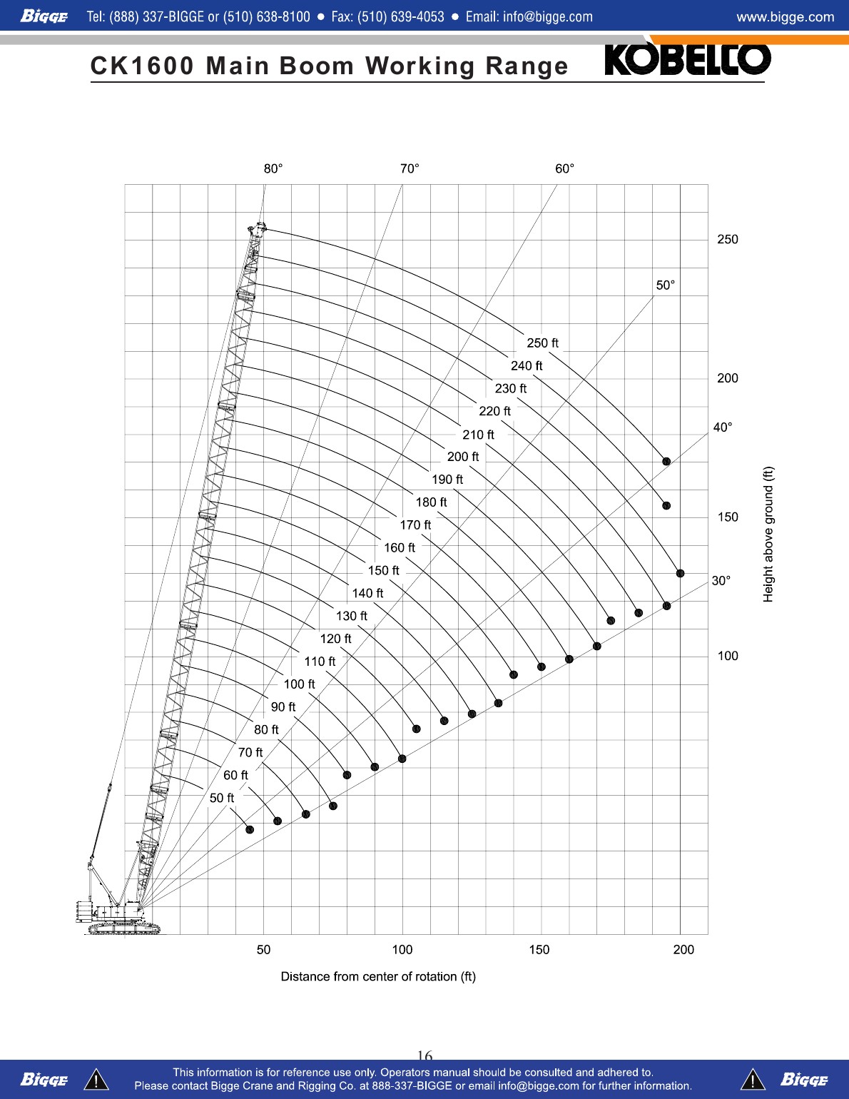
Focus viewEvery arc is one boom length. Longer boom reaches further and higher, and each step out along an arc is radius the chart charges for.
The main-boom working-range diagram connects boom length and angle to radius and boom-point height; it does not state capacity. Source: Supplied CK1600 Spec Book PDF p17, main-boom working rangeOpen the complete controlling page
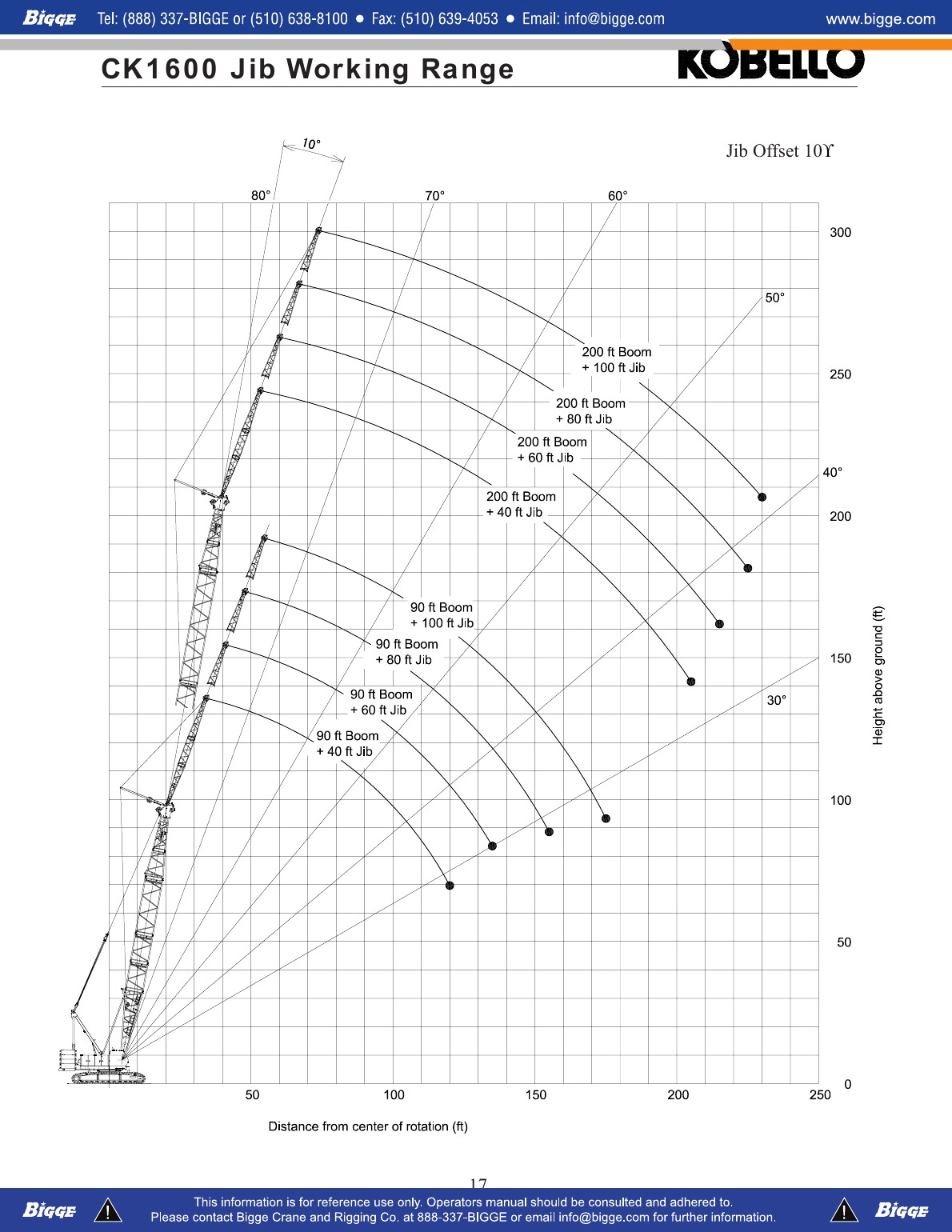
Focus viewJib working range at 10 degree offset: 90 ft and 200 ft boom, each with 40, 60, 80 and 100 ft of jib. A jib buys height and reach; every one of these combinations has its own chart.
The 10-degree fixed-jib range diagram shows how boom and jib combinations change reach and elevation. Source: Supplied CK1600 Spec Book PDF p18, 10-degree jib working rangeOpen the complete controlling page
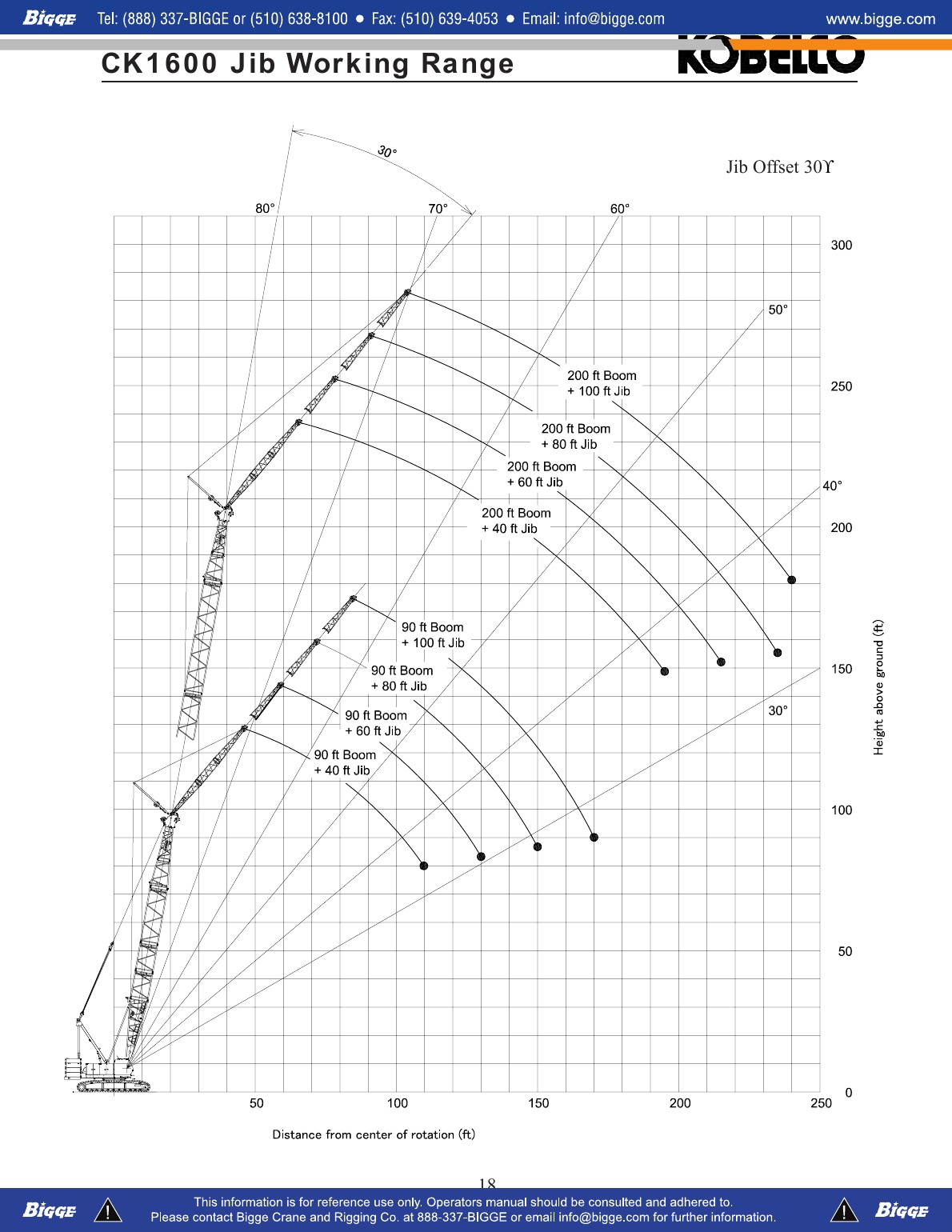
Focus viewThe same combinations at 30 degree offset. More offset, more reach at the tip, and a different chart again - the offset is part of the chart's identity.
The 30-degree fixed-jib range diagram must be paired with the matching offset and capacity table. Source: Supplied CK1600 Spec Book PDF p19, 30-degree jib working rangeOpen the complete controlling page
Boom length, ft
Capacity at the shortest charted radius, lb
Greatest charted radius, ft
50
320,000
45
100
183,400
90
150
112,600
135
200
75,100
175
230
58,800
200
250
50,200
195
Maximum boom
250 ft
Maximum boom and jib
200 ft boom + 100 ft jib
Greatest radius charted
200 ft (on the 230 ft boom)
Jib rated loads
capped at 59,000 lb by 2 parts of rope
Where the angle stops you
On the overhoist side in crane mode the controller stops the boom at 80.0 to 80.5 degrees, and the boom overhoist limit switch stops it at 82 +/- 0.5 degrees. In self-removal mode the controller allows 86 degrees and the left backstop switch stops it at about 90. On the over-lowering side the stop angle varies with boom length and is set by the controller from the configuration you entered — so the low-angle limit is not one number to memorise, it is a consequence of the configuration.
The range diagrams
Three working-range diagrams: main boom, jib at 10 degrees offset, and jib at 30 degrees offset. That is where you go to find the boom length and angle that reach a required radius and height — the chart tells you what you may lift there, the range diagram tells you whether you can get there at all.
Spec Book PDF p17–p19 (working range) · PDF p21–p23 (main boom rated loads) · PDF p24–p29 (jib rated loads) · O&M PDF p136 (3.7.2 inspection after erecting the attachment)Reference O&M p136
What the indication is worth, and why radius grows
Computed by the controller and displayed continuously
Boom angle, degrees
Boom angle detector on the boom, displayed continuously
Boom point elevation, feet
Controller display
Actual load and rated load, lb x1000
Load detector pin, against the rated load for the configuration entered
Lifting height (option)
Gauge cluster multi-display
Wind velocity and wind alarm set point (option)
Gauge cluster multi-display
Wire rope layers on front and rear drum
Gauge cluster multi-display
No published accuracy for any of it
Neither primary document publishes an indication accuracy tolerance. Treat the readouts as a cross-check on a measured radius, not as a replacement for measuring one. Radius estimated by eye, or taken off a plan drawing, is the named error here.
Radius is not a constant
Load radius is measured from the centre of rotation to the load's centre of gravity with the boom loaded. That distinction is the whole point: taking the load deflects the boom and settles the machine, so the loaded radius is always greater than the unloaded one. It grows further if the ground yields under a track, if the machine is out of level, and every time the load swings. The radius you planned with is the smallest one you will see. And a load that must be walked out to be landed can be inside the chart at the pick and outside it at the set.
O&M PDF p49–p53 (gauge cluster) · PDF p102–p106 (controller display) · PDF p18, p23 · Spec Book PDF p20 (chart note: deflection is not included)Reference O&M p49
Spec book note 6: the weight of hooks, hook blocks, slings and other lifting devices is part of the total load, and their total weight must be subtracted from the rated load to obtain the weight that can be lifted.
Focus viewNote 6: hooks, blocks, slings and lifting devices are part of the load and come off the rated load. The table under note 7 is the jib and auxiliary-sheave deduction this module uses.
The chart notes define gross load, deductions, configuration, levelness, reeving limits, least-stable direction, and conditions that require derating. Source: Supplied CK1600 Spec Book PDF p20, Supplemental DataOpen the complete controlling page
Deduction
Value
Auxiliary sheave mounted
1,250 lb
40 ft jib mounted
7,055 lb
60 ft jib mounted
8,010 lb
80 ft jib mounted
8,965 lb
100 ft jib mounted
9,920 lb
Hook block, ball, slings, shackles, spreader
weigh them
Mounted is mounted
The jib and auxiliary sheave deductions apply when the attachment is mounted, whether or not you are lifting on it. And the total on the auxiliary sheave is the boom rated load minus 1,250 lb, never exceeding 59,000 lb — its rope is limited to two parts.
Chart capacities are gross. Everything hanging on the machine comes out of them, and the order of these steps matters as much as the arithmetic.
What comes off the gross chart value on this machine, and what is still unmeasured
GrossGross rated load, read from the chart row
− Jib mounted7,055–9,920 lb, by jib length · p20
− Auxiliary sheave1,250 lb · p20
− Hook blocknot recorded: measure on the crane
− Headache ballnot recorded: measure on the crane
− Hoist ropenot recorded: measure on the crane
= Netcannot be completed while any block above is unmeasured
Drawn from this machine's documentsWhat comes off the gross figure on this machine. Two deductions are published; three are not recorded anywhere and come from the hardware on this crane. Until they are measured, the net figure cannot be completed. Recorded deductions: 2 · not recorded: 3 · Source: Spec Book PDF p20
Step
What you do
On this machine
1
Confirm the configuration the machine is actually in
Counterweight and carbody weights, boom length, jib and offset, auxiliary sheave, parts of line, gantry raised, backstops fitted
2
Select the one governing chart
Read its identification line. 117 charts; only one applies
3
Establish the radius by measuring
Loaded radius, centre of rotation to the load's centre of gravity
4
Read the gross rated load
The row for that radius on that chart
5
Subtract the published deductions
Auxiliary sheave 1,250 lb. Jib mounted, lifting over the boom point: 40 ft 7,055 · 60 ft 8,010 · 80 ft 8,965 · 100 ft 9,920 lb
6
Subtract the hardware
Hook block or ball, slings, shackles, spreader, below-the-hook device. These weights are not published by any manufacturer — read them off the hardware on this machine and record them
7
Apply the notes and footnotes
Including the asterisk, the quadrant guidance, and the blocking requirement at 240 ft boom and over
8
Compare and state percent of capacity
Against the total load, not against the bare load
The two deductions that are open here
Hook block and headache ball weights are not published and never will be — they are rigging hardware that varies by machine. The answer is on the crane, not in a book: read the weight stamped on this unit's block and ball, photograph the data plate, record them. Wire rope weight has no published deduction rule either; if the employer's planning deducts rope weight at long boom, that figure comes from the manufacturer or the rope supplier.
The forgotten deduction
The most common one is the attachment that has been on the machine so long it has become invisible — an auxiliary sheave, or a jib left pinned on. It is 1,250 lb or up to 9,920 lb off every capacity on the chart whether or not you remember it. And a block swapped for a heavier one without recalculating is the same failure with fresher paint.
Spec Book PDF p20 (supplemental data notes 6, 7, 10, 11) · deduction table PDF p20 · O&M PDF p112Reference O&M p112
Rated loads do not exceed 75% of the minimum tipping load. Loads limited by something other than stability — structural competence — are marked with an asterisk.
Focus viewThe asterisk beside a rated load marks a row limited by structural competence. Unmarked rows are limited by stability. Same column, two different failure modes.
The chart heading, radius, angle, gross rated load, and structural-limit marks must be read as one record. Source: Supplied CK1600 Spec Book PDF p21, main-boom rated loadsOpen the complete controlling page
Why that matters in the cab
A stability-limited load gives cues as it approaches the limit. A structurally limited load gives none. The machine will not lighten on its tracks, the LMI ratio is still the ratio — and then something fails. On this machine 185 of the 491 main boom rows carry the asterisk, concentrated at short radius and at the longest booms.
The other notes carry equal weight
Level within 1% · backstops required for all boom lengths · gantry fully raised for all operations · do not lift where no radius or load is listed · do not tip the machine to determine rated loads · jib mounts only on 90–200 ft booms · auxiliary sheave only on 50–240 ft booms.
Structural competence — the steel, not the tipping balance
Nothing. No lightening, no lean, no cue before it fails
No asterisk
Stability — rated loads do not exceed 75 percent of the minimum tipping load, machine level within 1 percent on a firm surface
The machine gets light and the indication climbs. There is a margin, and it is 25 percent of tipping
Where the boundary falls on this machine: the short radii are structural, and the structural region reaches further out as the boom gets longer.
Boom length, ft
First stability-limited radius, ft
50
none — the whole chart is structural
60
30
100
36
150
50
200
65
250
100
Why the distinction is not academic
A stability-limited row is one you might feel before you break it. A structural row is one you cannot. Pulling in to a shorter radius feels safer, and on these charts it moves you into the region where the warning goes away. On the 50 ft boom there is no stability-limited row at all — every capacity on that sheet is structural.
The other notes carry the same authority as the numbers
The charts are 360 degree ratings, but the least stable position is over the side, and the boom should be erected over the front of the crawlers, not laterally. At 240 ft boom or over, blocks must be placed at the end of the crawlers when lifting from or lowering to the ground. Rated loads apply only to the machine as originally manufactured — modification or non-specified equipment reduces capacity. Designed and rated to comply with ANSI B30.5.
Spec Book PDF p20–p23 (footnote, notes, main boom rated loads) · PDF p24–p29 (jib rated loads)
Verify configuration · select the chart · establish radius · read gross · subtract deductions · apply notes · compare to the total load · state percent of capacity. Written down, in that order, every time. The value of a fixed procedure is not elegance — it is that a missing step becomes visible.
Focus viewNote 1: rated loads assume the machine level on a firm supporting surface under ideal operating conditions. The user must limit or de-rate them for wind, side loads, out-of-level and the other conditions listed.
The chart notes define gross load, deductions, configuration, levelness, reeving limits, least-stable direction, and conditions that require derating. Source: Supplied CK1600 Spec Book PDF p20, Supplemental DataOpen the complete controlling page
What breaks chart work
Why
Time pressure
Steps get merged, and the one that gets dropped is usually a deduction
Poor light or a dense sheet
Reading across the wrong row produces a number that is real, plausible, and wrong
Working from memory
The worst of the three: a remembered capacity feels exactly like a looked-up one, and it was true for a configuration you are no longer in
A configuration change mid-shift
Boom length, jib pinned on, counterweight moved, parts of line changed — the chart work runs again from step one
Independent verification
A capacity determination gets checked by a second competent person, working the chart independently rather than reviewing your arithmetic. Two people arriving at the same number from the same chart is evidence; one person agreeing with another's number is not.
And the framing that matters most
Chart capacity is a limit, not a target. Everything this Area and the next one cover — wind, ground, dynamics, out-of-level, side load, deflection — erodes margin that the chart never contained. A lift planned at 100 percent of chart has no margin left for any of it. The manufacturer's own instruction is to reduce the load under adverse field conditions until, in the operator's judgment, the machine can safely handle the lift.
O&M PDF p18 (operating precautions 1) · rating chart rule PDF p14 · Spec Book PDF p20 (note 2: the user must limit or de-rate)Reference O&M p18
That is the manual's own first operating precaution, and the three factors it names are the whole of this Area: the radius, the weight of the load and hook and rigging, and the configuration.
Focus viewRead all capacity inputs together: radius, load and rigging weight, boom/jib, parts of line, and operating area.
The manual illustrates load radius from the center of rotation and connects capacity work to ground support. Source: CK1600 O&M PDF p18, Operating PrecautionsOpen the complete controlling page
The sentence that matters most
“Trying to lift a load without knowing whether it is within the rated capacity while expecting the crane to start to tip to warn of an overload is very dangerous and should never be done.” Cranes may suddenly tip over or collapse.
And the duty that follows it
“The operator must reduce the load under adverse field conditions until, in his judgment, the machine can safely handle the lift.” Not may — must.
Focus view(1) DISPLAY: actual load beside rated load, radius and the load ratio. The note under the controller says these numbers are an example only.
The installed controller layout distinguishes display, audible warnings, control switches, protected memory-card access, and adjustment switches. Source: CK1600 O&M PDF p102, LMI controller anatomyOpen the complete controlling page
What this machine can tell you
The LMI displays actual load alongside rated load and the moment ratio. Neither primary document publishes an indication accuracy, so it is a cross-check on a known weight — not a substitute for knowing it.
O&M PDF p18, p88, p102Reference O&M p18
What gets added after somebody wrote the weight down
The number on the drawing was true in the shop. Between there and the hook, things get added.
Focus viewLoad radius, from the center of rotation to the center of the load. Item (1) beside it: the radius will increase when the load is lifted.
The manual illustrates load radius from the center of rotation and connects capacity work to ground support. Source: CK1600 O&M PDF p18, Operating PrecautionsOpen the complete controlling page
Addition
Where it hides
Entrained water and mud
Forms, excavated material, anything that sat out in weather, anything craned out of a hole
Ice and snow
On the load, and on the boom and machine at the same time — none of it weighed
Residual contents
Tanks, pipe, vessels, hoppers. Empty is a claim, not a measurement
Attached hardware
Brackets, motors, valves, grating, bolting left in place
Packaging and dunnage
Crating, banding, pallets, protective steel
Below-the-hook devices
Spreader beams, lifting frames, magnets, vacuum lifters — part of the load, every time
Centre of gravity turns weight into radius
If the hook is not plumb over the load's centre of gravity, the load will not hang plumb. It will swing when it breaks the ground, and the radius you planned is not the radius you are working at. An offset centre of gravity also loads the slings unevenly — one leg takes far more than the arithmetic suggests. Liquids and loose contents move the point during the lift.
The two conditions that make a weight meaningless
A weight taken on someone's word, with no document and no traceable source, is not a weight. And a load that is restrained — frozen down, bolted, suction-bound, or attached to something else — has no weight at all until it is free. Breaking it loose with the hoist can tip the machine or collapse the boom, and the reading you get on the way is not the load.
O&M PDF p18–p23 (operating precautions) · Spec Book PDF p20 (note 6: hooks, hook blocks, slings and other lifting devices are part of the total load)Reference O&M p18
What the controller tells you, and the two things it does not
Percentage, with a bar scaled 60 · 70 · 80 · 90 · 100
Boom angle
Degrees
Boom point elevation
Feet
Actual load
Pounds x1000
Rated load
Pounds x1000
Working radius
Feet
Configuration line
Attachment type, counterweight, boom length, jib length, jib offset angle, hook in use, and parts of line for main and auxiliary
The controller menu and rated-load table screen show how the operator accesses the capacity data carried by the installed controller. Source: CK1600 O&M PDF p109, rated-load table displayOpen the complete controlling page
No published accuracy tolerance
Neither primary document publishes an indication accuracy figure. The video curriculum quotes about 2 percent; that is indicative only and is not a calibration criterion. So the standing instructions govern: operate within rated capacity, never guess a capacity between charted values, and never lift an unknown load expecting the machine to warn you by starting to tip. Verify indication against known weights under the employer's test policy.
No deduction entry field — and this one matters
There is no manual deduction entry on this controller. It computes actual load from the load detector pin and compares it against the rated load it looks up from what you entered. A conflict exists in the sources: Kobelco's CK1600 LMI walkthrough says the system automatically deducts blocks, balls and jib; the manual describes no such function, and the spec book puts the deduction squarely on the operator. Until a controlled known-weight test proves the behavior on this crane's own controller, teach and work the manual — the operator applies the deductions. Record the displayed actual/rated values, selected hook and configuration, and every applied deduction during that field test. An operator who believes the machine is deducting for him, when it is not, is over the chart and does not know it.
Keep indicated values and verified behavior separate
Displayed actual and rated values
Purpose: The lesson distinguishes actual load from the rated load looked up from the selected configuration.
Operator decision: Read the actual and rated values with the selected hook and full configuration.
Deductions on this crane
Purpose: The existing lesson records conflicting source claims about automatic deductions.
Operator decision: The operator applies the manual and chart deductions unless a known-weight test proves otherwise on this crane.
The manual and a manufacturer video disagree; this comparison follows the manual.
O&M PDF p102–p106 (3.4 function of controller/monitor) · PDF p112 (3.5.2 setting of the crane configuration) · Spec Book PDF p20 note 6 · OEM CK1600 LMI video GynA2j3wsBQ (conflicting auto-deduct statement; field verification required)Reference O&M p102
Every hook carries a latch that must work and must never be wired open. The latch retains slings under slack conditions — it is not an anti-fouling device and must never support any part of the load. Rigging is seated in the bowl of the hook, never against the latch.
Focus viewNote 6: hooks, hook blocks, slings and other lifting devices are part of the total load, and their total weight is subtracted from the rated load.
The chart notes define gross load, deductions, configuration, levelness, reeving limits, least-stable direction, and conditions that require derating. Source: Supplied CK1600 Spec Book PDF p20, Supplemental DataOpen the complete controlling page
Plumb before you pull
“The load will swing out of control if it is not directly beneath the boom point when lifted. This can side load the boom and may cause the crane to tip or collapse.” Always place the boom point directly above the load.
Everything below the hook is load
Slings, shackles, spreaders, below-hook devices — all of it comes off the chart with the block and the ball.
Main hook block and an auxiliary ball hook, each selected in the controller configuration with its own parts-of-line entry. The specification page quotes working weight with a 135 t hook block fitted.
Daily, at the start of each shift
Clean and lubricate
The block or ball, the sheaves where fittings are provided, the hook swivel, and every grease point at its interval
Block hardware
Sheave, bearing and wire lock for damage; bolts and nuts for falling off
The hook itself
Wear, deformation, the throat opening up, twist, and cracks
The rope end
Wear and broken wires where the rope enters the dead-end socket; the socket for cracks; dead-end clips tight
The latch
Present and operating. It must not be wired open or removed, must retain slings under slack conditions, and must never support any part of the load
At least yearly
Each hook and shackle checked for cracks by dye penetrant, magnetic particle, ultrasonic or X-ray. Do not repair cracks in hooks or shackles by welding.
Deduction
Value
Where it comes from
Auxiliary sheave mounted
1,250 lb from main boom rated loads. The auxiliary sheave's own total is the boom rated load without it, minus 1,250 lb, and must not exceed 59,000 lb. Fitted on booms 50 ft to 240 ft, maximum 2 parts of 26 mm rope.
Published
Jib mounted, lifting over the boom point
40 ft jib 7,055 lb · 60 ft 8,010 lb · 80 ft 8,965 lb · 100 ft 9,920 lb
Published
Hook block and headache ball
Not published, and never will be — they are rigging hardware that varies by machine. Read the weight stamped on this unit's block and ball and record it. The answer is on the crane, not in a book.
Not published
Hoist rope weight
No weight-per-foot or rope deduction rule is published. If the employer's planning deducts rope weight at long boom, the figure must come from the manufacturer or the rope supplier.
Not published
Two ceilings, not one
Parts of line cap the rope, not the machine: 29,500 lb per part. Eleven parts gives 320,000 lb — not 324,500, because the machine's maximum capacity caps it. Jib and auxiliary sheave are limited to 2 parts, so 59,000 lb is the ceiling on either. The rope table limits what the rope can lift; the rated load chart limits what the machine can lift; the lower of the two governs.
O&M PDF p272–p273 (hook maintenance standard) · PDF p115 · Spec Book PDF p20 (supplemental data notes 6, 7, 10, 11, 14)Reference O&M p272
Bring the load line plumb over the load's centre of gravity before taking the load. A line off plumb drags the load sideways as it breaks the ground and puts bending into a lattice boom built to take compression. The chart for this machine assumes a freely suspended load with the line plumb, and permits no side loading — so there is no allowance to spend on it. Named sources of side load: out-of-plumb line, swinging load, dragging, wind, and an out-of-level machine.
Focus viewNote 1: the charts rate freely suspended loads. Side loads, pendulum action, and jerking or sudden stopping of loads are among the conditions the user must de-rate for.
The chart notes define gross load, deductions, configuration, levelness, reeving limits, least-stable direction, and conditions that require derating. Source: Supplied CK1600 Spec Book PDF p20, Supplemental DataOpen the complete controlling page
Sling angle, from the seat
As the angle between a sling leg and the horizontal gets smaller, tension in that leg rises steeply — the load has not changed and the slings are working far harder. The operator-visible cues are legs that look close to horizontal, sling legs reaching a long way out to pick points, and hardware that starts to draw down or deform as you take up. If it looks flat, it is.
What you do not do with the machine
Do not drag a load, and do not break a load free with the boom or the hoist. A load that is frozen, bolted or suction-bound can tip the machine or collapse the boom when it releases — or not release at all while the indication climbs.
The stop
Rigging the operator can see is wrong gets stopped by the operator. That is a duty, not a preference, and it does not require winning an argument first. The same goes for hands and body positions during take-up, lift-off and landing: nobody's hands on the rigging as it comes tight, nobody under the load, nobody in the fall zone.
O&M PDF p23 (side loading) · PDF p18–p22 (operating precautions) · Spec Book PDF p20 (chart notes: freely suspended, side loads)Reference O&M p23
It is a value at every point of the pick, the swing and the set. The chart is read at the greatest radius the load will occupy — which is frequently the set, not the pick.
When a signal person is required
The manual names it specifically: near power lines, where a signal person maintains the safe distance because the operator is not in the best position to judge distances; in close quarters while travelling; and while propelling the machine.
Blind picks
When the operator cannot see the load, the lift depends entirely on signal quality. Position, relay arrangements and a common protocol are agreed before the load moves — not improvised once it is off the ground.
Counterweight arrangement and carbody weights, boom length, jib and offset, auxiliary sheave, parts of line, gantry raised, backstops fitted
The chart
The one chart that matches that configuration — identified, not assumed
The load
Weight and its source, plus every deduction: jib, auxiliary sheave, block, ball, below-the-hook device
The rigging
Slings, angles, hardware, and the weight of all of it
Radii
At the pick, through the swing, and at the set — every one of them
Capacities and percent of capacity
At each of those radii, from that chart
Ground
Bearing capacity, mats or plates, levelness within tolerance, trenches shored or sloped
Hazards
Power lines, structures, adjacent equipment, channelled wind
Sequence
The order of operations, and the hold points
Personnel
Signal person, riggers, and who is authorised to stop
The failure that keeps happening
A plan built on the pick radius alone, with the set radius never checked. The lift was legal when it left the ground and over capacity when it arrived. Capacity is evaluated at every point in the pick, swing and set, and the worst of them governs the lift.
Hold points, and what changes them
The plan names the points at which work stops for verification before proceeding — setup verified against the plan, load weight confirmed, test lift held and read, and confirmation at the set before the line is slacked. Field conditions that differ from the plan require going back to the plan, not around it. A plan changed verbally in the field with no re-verification of capacity is not a plan.
Where the classification comes from
The manufacturer defines no critical-lift threshold for this machine. Percentage of chart, tandem lifts, personnel lifts and blind picks are classified by the employer's lift-planning policy and the governing regulation. What the manufacturer imposes instead is a standing duty: operate within rated capacity, take the next lower charted value when boom length or radius falls between figures, and reduce the load under adverse field conditions.
O&M PDF p16 (pre-job planning questions) · PDF p18 (operating precautions 1) · rating chart rule PDF p14 · Spec Book PDF p20Reference O&M p16
Unambiguous control of the load is a system, not an attitude. Three rules carry most of it.
Rule
In practice
All signals come from the designated signal person
One voice, one set of hands, agreed before the lift. Not whoever is closest to the load.
A stop signal is honoured from anyone
You do not check standing first. Stop, then find out why. This is the one signal with no designated source.
An unclear signal is a stop
Not a guess, not a small movement to see what they meant. Unclear means stopped.
Stop, emergency stop, dog everything
Three distinct signals worth knowing as three distinct things: stop ends the motion, emergency stop ends every motion now, and dog everything means secure and hold the machine as it stands. They mean different things to the operator, so they are given and read as different signals.
Where the signal set comes from, since it is not in here
This manual requires a signal person and says to sound the horn before propelling. It publishes no hand-signal chart and no voice protocol. So the standard signal set is the governing standard's and the employer's programme's, not the manufacturer's — which means the set in use has to be named in the lift plan and agreed before the lift, not assumed to be the one you learned somewhere else.
Lost communication mid-lift
Loss of visual or radio contact is a stop, at the first point the load can be held or landed safely — not a reason to complete the move you had planned. Contact is re-established before anything moves again.
Blind picks
When the operator cannot see the load or the landing, the lift is running on the signal person's eyes, and their position becomes part of the plan: where they stand, what they can actually see, and whether a relay signaller is needed. Relay signalling adds a link, and every link is somewhere a message can change on the way through — so the plan says who relays to whom, and in what words.
O&M PDF p16 (pre-job planning questions) · signal person required PDF p72–p73 · stay-away decal PDF p9. The hand-signal set itself is NOT in this manual — see the note above.Reference O&M p16
“Rapid swings or sudden starts and stops can cause the hook and attached load to swing out of control. Always start and stop movements smoothly and swing at speeds that will keep the load under control.”
Two elements prune
Telescoping technique and its risks do not exist on a lattice boom. What is left is entirely about drums, swing, propel and the load on the end of the line.
Lever direction is adjustable
Section 2.3.2 lets the control lever direction be changed on this machine. That means the direction a lever moves a function is a setting, not a fact — and must be verified on the machine you are on, every time.
Swing; red horn button and parking swing brake switch in the grip. Parking brake is never applied while swinging
Two propel levers, with lock
Travel — pivot, counter-rotate, wide turn
Function lock lever
LOCK disables every function
Drum lock knobs
Mechanical drum locks
Drum brake pedals
With lock positions
INCHING
Drums and propel to ¼, boom drum to ⅙
Swing mode
FREE/HIGH · FREE/LOW · BRAKE/LOW
Propel speed
HIGH for good ground · LOW for tractive effort
The complete operator-station map provides orientation before individual controls are taught. Source: CK1600 O&M PDF p35, operating-control location mapOpen the complete controlling page
O&M PDF p35–48, p67–87 · OEM CK1600 Operating Controls video HO3t-4FmFPw (visual corroboration only)Reference O&M p35
There is no two-axis joystick pattern on this machine. Each function has its own lever, and they are spread across two consoles, the floor, and a side stand panel.
The left-side stand panel identifies locks, release controls, automatic-stop check, emergency stop, mode selection, and hydraulic selectors. Source: CK1600 O&M PDF p36, left-side stand panelOpen the complete controlling page
Control
Function
Where
Boom drum lever (inching switch in the grip), plus boom drum pedal
Boom hoist raise and lower
Right console; pedal at the floor
Front drum lever
Main hoist raise and lower
Right console
Rear drum lever
Auxiliary hoist raise and lower
Right console
Third drum lever (option)
Third drum / luffing jib drum
Left console
Swing lever — red horn button and parking swing brake switch in the grip
Push for left, pull for right. Parking brake is for parking only; never apply it while swinging.
Left console
Left and right propel levers, with lever lock
Travel, proportional to push and pull. Forward is toward the idler, backward toward the propel motor. Both levers give pivot turn, counter rotation and wide radius turn.
Front of the seat
Accelerator grip (120 degrees of range); auxiliary accelerator with by-pass switch
Engine speed; the auxiliary is the backup path if the grip fails
Right console; auxiliary under the seat
Function lock lever
LOCK disables every operating function. Must be LOCK whenever leaving the seat.
Left of the seat
Drum lock knobs — front, rear, boom, third
Mechanical drum locks
Left side stand panel
Drum brake pedals with lock positions
Drum brakes
Floor
Drum brake selector switches
Select drum brake mode, including free fall
Right side
Drum speed adjusting knobs
LOW to HIGH trim, per drum
Drum speed control trimmer box
Key switch (OFF · ACC · ON · START)
Two steps right to ON, one more to START; two steps left to OFF
Left side stand panel
Engine emergency stop switch
Press once to stop the engine. It latches; reset by turning it right.
Left side stand panel
Swing lock control lever (option)
Mechanical house lock. Push to lock, pull to unlock; set for parking and transport.
O&M PDF p35–p48 (2.2 control locations and operating switches) · PDF p67 · PDF p71 · OEM CK1600 Operating Controls video HO3t-4FmFPw (visual corroboration only)Reference O&M p35
The pattern is a setting, and the interlocks have opinions
The lever direction is adjustable on this machine — there is a documented procedure for changing it. So which way a given lever moves a function is a machine-specific setting, not a property of the model. Verify the configured direction of every lever on this unit before operating, and re-verify after any service. Assuming direction from another crane of the same type is the named error here.
The three swing modes are defined by both speed selection and whether braking occurs when the lever returns to neutral. Source: CK1600 O&M PDF p39, swing brake mode selectorOpen the complete controlling page
Interlock
Behaviour
Function lock lever
In LOCK the machine does not operate even if a lever is moved accidentally. If it is set to LOCK while a lever is being operated, drum rotation stops and will not restart on returning to WORK until that lever has first been returned to neutral.
Propel control lever lock
Engage when you do not want the machine to travel.
Release switch master key
In LOCK, all three release switches are disabled and the key can be removed.
Release switches
Spring-returned. A stop is released only while the correct switch is held; operating an unrelated release switch does nothing.
Backstop limit switch stop
Cannot be released by the boom overhoist release switch.
Boom drum lock warning
Stop the engine with the boom drum lock released and a buzzer sounds for about four seconds. W-31 appears whenever the engine stops.
Swing parking brake
Not applied by the brake mode selector alone — it is applied with the swing brake switch on top of the swing lever.
Automatic stop check switch
While held, boom raising, boom lowering and hook raising are made unavailable, so the stop function can be proved.
O&M PDF p67 (2.3.2 adjusting the control lever direction) · control locations PDF p35 · interlocks PDF p40, p43, p71, p93Reference O&M p67
Three separate things hold a drum on this machine, and one switch can take the holding away entirely.
Match the selector with the drum indication
The OEM figure separately identifies brake selectors and free-fall indicator lamps. Other drum holding devices remain distinct.
Enlarge numbered diagram
Scroll across the enlarged source image to read its labels and the added study numbers.
The OEM figure separately identifies brake selectors and free-fall indicator lamps. Other drum holding devices remain distinct. Numbered study labels have been added to the source image; they are separate from OEM numbering. Enlarge complete source page
1. Front and rear drum brake-selector switches
Purpose: Free fall is armed per drum through its brake-selector switch.
What the source shows: The source identifies front and rear selectors separately; the third selector is an option.
Operator decision: Identify the actual drum and configuration rather than assigning one selector's state to every drum.
Source PDF page(s): 37
2. Free-fall indicator lamps
Purpose: The separate lamps show the free-fall indication for the front, rear, and optional third drum.
What the source shows: The labels above the gauge cluster identify each drum.
Operator decision: Read the relevant drum's indication alongside the complete mode and lock instructions. Do not import CK1100G control behavior.
Source PDF page(s): 37
CK1600 O&M PDF p37, brake selectors and indicators · CK1600 O&M PDF p37. Existing lesson limitations, free-fall lock requirements, and optional-equipment verification remain unchanged.
The diagram makes the brake-disk indicator inspection observable by separating free-fall protrusion, pressed measurement, and the zero-length failure condition. Source: CK1600 O&M PDF p251, free-fall brake disk indicatorOpen the complete controlling page
Recognize the separate holding devices
Complete procedures and employer test criteria remain required.
Hydraulic brake
Purpose: Per drum, with a brake selector switch
Operator decision: Prove the load brakes daily: lift a load a few inches off the ground and hold it.
Foot brake pedal
Purpose: Per drum, with a lock position
Operator decision: If pedals and locks are in use, always keep your feet on the pedals.
Mechanical drum lock
Purpose: Knob on the left side stand panel
Operator decision: Engaged before starting and before stopping the engine.
O&M PDF p251 (drum brake disk) · PDF p82–p84 (2.4 free fall operation) · pedals PDF p24 · load brake test PDF p17 · adjustment PDF p323–p325
Reading the brake disk indicator
In free fall mode the indicator protrudes approximately 17 mm (5/8 in.). With the engine stopped and the indicator pressed, 2.5 to 3.0 mm (3/32 to 1/8 in.) of protrusion is normal. 0 mm means winching may be impossible and the disk must be replaced. Lower the hook block to the ground before checking, so it cannot drop while you are at the indicator.
Free fall, and the rule attached to it
Free fall is armed per drum by the brake selector switch, shown on the free fall indicator lamps, and gated by the free fall lock switch. The free fall speed acceleration selector must never be HIGH for free fall of heavy loads or for non-crane work such as wire reeving — a great shock occurs when the speed is changed, and with the brake released in HIGH the drum pays out without load. Return it to NORMAL when spooling out wire rope. Inching does not apply to a drum in free fall. If a drum clutch emergency trips, free fall on that drum will not work normally.
O&M PDF p251 (drum brake disk) · PDF p82–p84 (2.4 free fall operation) · pedals PDF p24 · load brake test PDF p17 · adjustment PDF p323–p325Reference O&M p251
Lowering the boom increases radius, and increasing radius reduces capacity. A lift that is inside the chart at 40 ft can be outside it at 60 ft — so booming down with a load is a capacity change, checked before it is made, not a positioning adjustment.
Focus viewDrum clamp: the plate tightening torque, 373 N-m (275 ft-lbs), the painted section of rope at the clamp, and a rope end that must not stick out of the drum flange.
The maintenance diagram shows the drum-flange attachment, correct wedge orientation, and the tighter three-line minimum at the drum. Source: CK1600 O&M PDF p235, winding wire rope onto the drumOpen the complete controlling page
Two-blocking during combined motions
“Two blocking can be caused by hoisting the hook into the end of the boom or lowering the boom without paying out load line.” The second is the one that surprises people. It can pull jibs and lattice booms over backwards or cause structural damage at the boom or jib points.
Spooling
Wind on with light taps and steady tension so the rope beds tightly. Keep at least three lines on the drum. Check daily that the drum clamp bolts are tight — 373 N·m (275 ft-lb) — and that the painted section of rope is correctly positioned.
Abrupt input generates dynamic load the chart does not contain. This machine gives you four ways to be gentle on purpose.
Control
What it does
Inching speed switch (boom hoist lever grip)
Front drum, rear drum and propel reduced to about 1/4 of normal; boom drum to about 1/6. Not effective while that drum is in free fall mode.
Drum speed adjusting knobs
Continuous LOW to HIGH trim for front, rear, boom and third drums — set the working range before the pick, not during it. Optional front/rear drum-turn grips move and click with drum rotation; confirm whether this crane has them.
Swing brake mode selector
FREE/HIGH, FREE/LOW, BRAKE/LOW. In BRAKE/LOW the operating brake applies when the lever returns to neutral. Do not confuse that selector with the separate parking swing brake switch, which must never be applied while swinging.
Propel speed selector
HIGH for good ground; LOW when tractive force is required on bad ground. In HIGH, pivot turn and counter rotation may not be possible depending on ground conditions and engine speed.
Mode selector switch (B)
HIGH for normal work, LOW for special work — used when the front and rear drums are hard to tune for heavy work and clamshell operation.
Swing, and the pendulum you start
A suspended load is a pendulum whose period follows line length, not weight. Accelerating a swing puts the load behind the boom point; decelerating throws it ahead, out to a radius that is on no chart. The load out of plumb is also a side load into the boom. Ease in, ease out, and let the load catch up before you stop.
O&M PDF p36, p43 (operating switches) · speed modes PDF p35–p48 · propel cautions PDF p72–p73 · side loading PDF p23 · OEM CK1600 Operating Controls video HO3t-4FmFPwReference O&M p36
Focus viewLocate the minimum-wrap instruction before discussing payout limits.
The safety-practice page illustrates minimum rope remaining on the drum, brake use, stored hydraulic pressure, and pin-connected boom hazards. Source: CK1600 O&M PDF p24, rope wraps and pinned-boom precautionsOpen the complete controlling pageThe maintenance diagram shows the drum-flange attachment, correct wedge orientation, and the tighter three-line minimum at the drum. Source: CK1600 O&M PDF p235, winding wire rope onto the drumOpen the complete controlling page
A documented conflict, carried openly
The reeving chapter states that at least three lines of wire rope must be on the drum, and do not unwind further once only three lines remain — with fewer than three the rope may come unfixed and drop the load. Operating Precaution 21 in the safe-practices chapter states keep at least two full wraps on drums when operating. Three is carried here as the tighter of the two. The conflict is on the open-questions list, not resolved by preference.
Why crossed wraps matter
Loose or crossed wraps crush and cut the rope in the layer beneath them, and they change the effective drum diameter — so the line pull and the line speed you expected are not the ones you get. Layer 7 is storage only on the front and rear drums.
Keep the source conflict visible
The authored lesson carries the tighter three-line requirement while the conflict remains on the open-questions list.
Reeving chapter
Purpose: At least three lines must remain on the drum; do not unwind further once only three remain.
Operator decision: Carry the existing tighter requirement and the applicable reeving instruction.
Safe-practices chapter
Purpose: Operating Precaution 21 states at least two full wraps while operating.
Operator decision: This wording does not erase the documented conflict or authorize reducing the course requirement.
CK1600 O&M PDF p24 and PDF p235.
O&M PDF p235 (6.1.2 winding wire rope onto the drum) · conflicting two-wrap rule PDF p24 · Spec Book PDF p6 (drum storage data)Reference O&M p235
The documents give principles rather than tolerances here. The tolerances belong to the evaluator and the employer's programme; the principles are not optional.
Focus viewItem 23: lower the load to the ground and the boom onto proper cribbing before maintenance or repair. A suspended hook or load, or a raised boom, can release machinery and let it move.
The safety-practice page illustrates minimum rope remaining on the drum, brake use, stored hydraulic pressure, and pin-connected boom hazards. Source: CK1600 O&M PDF p24, rope wraps and pinned-boom precautionsOpen the complete controlling page
Situation
What is required
Landing on an uneven or yielding surface
Confirm the load is stable and supported before slacking the line. Slacking early on a load that has not settled is how a load shifts, rolls, or takes a sling with it.
Damping swing
Use the geometry, not force — a correction that fights the pendulum feeds it. Line length sets the period; the shorter the line, the less time you have to be smooth.
Taglines
A tagline controls orientation. It does not control a load the wind is pushing, and it puts a person inside the fall zone if it is used badly.
Blind picks
The lift runs on the signal person's eyes. Signal quality becomes part of the machinery — a lost signal is a stopped lift, not a guessed one.
Travel with anything on the hook
Confirm people and obstacles are clear, sound the horn, use a signal person, and be especially careful with a long boom, a high boom angle, uneven ground, or a load up. Do not start or stop travel or steering abruptly. Radius will increase when the load is lifted.
Personnel
Nobody under the load and nobody in the fall zone. Ground personnel stay away from the machine.
And the habit that ends every sequence
Land the load before you do anything else — before maintenance, before checking a brake disk, before leaving the seat, and in every abnormal situation this manual addresses. Then the function lock lever goes to LOCK.
O&M PDF p16–p33 (safety, operating precautions) · propel cautions PDF p72–p73 · leaving the machine PDF p71 · fall zone PDF p9 (stay-away decal)Reference O&M p16
The test lift, and what the machine says while you hold it
A near-capacity lift is not a normal lift done carefully. It is a different procedure, and the first part of it happens with the load a few inches off the ground.
Loading ratio
Indication
What happens
90 percent
Indicator yellow, buzzer intermittent — the interval between beeps shortens as the moment ratio increases
Warning only. No automatic stop. This is the last warning you get.
100 percent
Indicator red, buzzer continuous, optional overload alarm lamp red
The machine is stopped automatically.
The gating nobody expects
Warning buzzers are issued only while a control lever is being operated in the more dangerous direction. Nothing sounds with the levers in neutral, or while you are moving in the safe direction. A quiet cab at 90 percent is not evidence of anything.
Working-area limit
Warning point
Set load limit
90 percent of the set limit
Angle limit
5 degrees before the stop point, unless a prenotice point was set
Radius and height limits
1 foot (1 m) before the stop point, unless a prenotice point was set
The standing duty, since there is no critical-lift threshold here
The manufacturer defines no critical-lift threshold. What is imposed instead: always operate within rated capacity; use the next lower rated capacity when the boom length or radius falls between charted figures, and never guess a value between them; and reduce the load under adverse field conditions until, in the operator's judgment, the machine can safely handle the lift. Critical-lift classification is the employer's policy and the governing regulation, not the manufacturer's.
O&M PDF p103 (3.4-2 buzzer) · warning and automatic stop table PDF p124 · working area PDF p118 · PDF p18 (operating precautions 1) · rating chart rule PDF p14Reference O&M p103
Spec book note 1: rated loads are the maximum allowable freely suspended loads, for a machine standing level on a firm supporting surface, under ideal operating conditions.
And the sentence after it
“The user must limit or de-rate rated loads to allow for adverse conditions” — and it names them: soft or uneven ground, out-of-level, wind, side loads, pendulum action, jerking or sudden stopping of loads, inexperience of personnel, multiple machine lifts, and travelling with a load.
Who does the de-rating
Not the chart, not the LMI. The user. Every one of those nine conditions is an adjustment the operator and the planner make, and none of them is in the printed number.
Stop work when the instantaneous wind velocity exceeds 10 m/sec (33 ft/sec, about 22 mph). It applies to the machine as configured — the manual gives one figure, not a table by boom length.
The manual distinguishes ground wind from elevated boom wind, identifies the measurement point, and states the instantaneous operating stop threshold. Source: CK1600 O&M PDF p32, wind cautions and measurementOpen the complete controlling page
Where it is measured
With the anemometer on the boom tip or tower cap where one is fitted. Otherwise a weather report figure is converted to instantaneous speed using the Beaufort chart. The working point of the wind is taken at the height above ground corresponding to 60% of the boom length — not at ground level, and not at the tip.
The number you can feel is the wrong number
Wind velocity differs between the ground and the high air, and between open ground and a city. A hand-held reading at the cab is not the wind the boom is in.
A limit you measure in the wrong place is not a limit. This manual is specific about where the governing wind is.
The manual distinguishes ground wind from elevated boom wind, identifies the measurement point, and states the instantaneous operating stop threshold. Source: CK1600 O&M PDF p32, wind cautions and measurementOpen the complete controlling page
Question
What the manual says
What is the limit?
Stop work when the instantaneous wind velocity exceeds 10 m/sec — 33 ft/sec, about 22 mph.
Measured where?
At the height above ground corresponding to 60 percent of the boom length at that time. Wind differs between ground and high air, and between flat ground and city air.
Measured how?
The anemometer on the boom tip or tower cap if one is fitted. Otherwise convert a weather-report figure to instantaneous wind speed using the Beaufort chart and conversion table.
Beaufort band, m/sec
What it looks like on land
5.5 to under 8.0
Dust, leaves and loose paper lifted; twigs move
8.0 to under 10.8
Leaves in small trees begin to sway — the 10 m/sec stop-work limit falls inside this band
10.8 to under 13.9
Larger branches moving, whistling in wires, hard to walk under an umbrella
13.9 to under 17.2
Whole trees moving, resistance felt walking against the wind
The limit is a ceiling, not a permission
Below the limit you still must not lift if wind creates a hazard, and must lower the boom if necessary. Moderate wind is a hazard for long booms and for loads with large surface area.
O&M PDF p32 (cautions for wind, method of wind velocity measurement) · hazard rule PDF p22 · Beaufort table PDF p31–p32Reference O&M p32
Sail area, the empty boom, and the number that does not exist
No numeric capacity reduction by wind speed is published in this manual. If a planned lift needs reduction factors, they must come from the capacity chart notes or from the manufacturer. Inventing a percentage is not planning.
The three mechanisms named
Wind influence grows in proportion to the size of the lifted load, the lifting height, and the boom length. A load of wide area with hard wind on it can overturn the machine or damage the boom, and can be blown against the boom. And a fully raised boom with no load can be blown backwards into an overturn — the empty boom is not the safe case.
Why sail area beats weight
A light panel and a heavy compact billet are the same number on the chart and nothing like the same lift. The chart accounts for the mass. Nothing on it accounts for the area the wind is pushing on, or for the fact that a large-area load will not hang plumb in a crosswind — which puts a side load into the boom that the chart also does not include.
A limit the manual does not give
This machine has no published out-of-service wind limit and no boom-down-and-secure threshold for an approaching storm. The lightning procedure says to lower the boom to the ground where it can be lowered, and that is the closest thing to one. If a boom is left standing overnight, the employer's severe-weather plan must set that threshold. The manual is silent is not an operating position.
O&M PDF p31 (influence of wind) · limit PDF p32 · hazard rule PDF p22 · lightning PDF p30Reference O&M p31
No absolute machine minimum is stated. The extreme-cold provisions run to -40 C, and they are about consumables and timing rather than capacity.
Item
Extreme-cold provision
Engine oil
Match viscosity to ambient: SAE 10W-30 for 40 C to -30 C; SAE 30 for 40 C to 0 C. API CD, CE, CF, CF-4, CH-4 or CI-4. Do not mix brands or qualities.
Fuel
Match to ambient; ASTM 2-D diesel only. Drain water before starting work, and fill the tank as full as possible after work.
Coolant
Mix by the published table: 4 litres of antifreeze (10 percent) for -4 C, rising to 20 litres (50 percent) for -40 C in the 40 litre system. Ratios vary by brand.
Battery
Keep it fully charged, specific gravity above 1.22 — a charged battery resists freezing far better. After adding distilled water, run the engine to mix water and electrolyte.
Engine warm-up
Double the normal 5 to 10 minutes.
Free fall
A light load may lower slowly. With the drum lock engaged, winch down about five minutes to warm the oil.
Codes that mean weather
Two cold-weather fault codes that are not faults: the winch cooling line filter code can appear without a clog and needs no cartridge if it clears during warm-up, and the engine preheat code simply means coolant was at or below 0 C at key-on.
O&M PDF p317 (7.6 operation under unusual conditions, extreme cold) · warm-up PDF p70 · free fall PDF p84 · codes PDF p54–p55Reference O&M p317
Extreme heat, and the storm that arrives during the shift
No absolute machine maximum is stated. Engine oil SAE 40 above 40 C (104 F). Do not use Long Life Coolant — mix anticorrosive with fresh water and wash out the radiator interior. Keep battery electrolyte 10 mm (0.39 in.) above the plates. Hydraulic and drum-clutch overtemperature are handled by the W-12, W-13, W-14 and W-18 fault codes rather than by an ambient limit.
Focus viewFollow the lightning sequence in order: stop, land or lower, secure, isolate, and clear personnel.
The manual's sequence for lightning or earthquake begins with stopping work, landing the load where possible, securing brakes and locks, and isolating power. Source: CK1600 O&M PDF p30, lightning and earthquake measuresOpen the complete controlling page
Step
Lightning anticipated, or an earthquake
1
Stop work and lower the load onto the ground. Lower the boom (or tower) onto the ground if it can be lowered.
2
Engage the brakes and locks — winch and swing — stop the engine, then turn off the power source of the load safety device and the main switch.
3
Advise all personnel to stay away from the area around the machine.
Before operating afterwards
Both events then require the same thing before the machine works again: check for burns and damage, check the electrical devices and the load safety device for performance, and check each function for abnormality.
The one this Area adds
Ice and snow are weight you did not weigh, on the boom, on the load and on the machine — and they change footing under the tracks at the same time. Ground assessed dry is a different surface after rain, after a thaw, or after a freeze. The setup assessment has a shelf life.
O&M PDF p318 (7.6-2 operation in extreme heat) · PDF p30 (measures for lightning, measures for earthquake) · codes PDF p55Reference O&M p318
None of this is inference. These are the notes on the rated capacity charts for this machine, and each one is a condition you can be outside of without the chart changing.
The chart notes define gross load, deductions, configuration, levelness, reeving limits, least-stable direction, and conditions that require derating. Source: Supplied CK1600 Spec Book PDF p20, Supplemental DataOpen the complete controlling page
The note
What it means at the levers
Rated loads are the maximum allowable freely suspended loads at a given boom length, boom angle and radius, for the machine standing level on a firm supporting surface under ideal conditions.
Every word is a precondition. Not plumb, not level, not firm, not free — not this chart.
The user must limit or de-rate rated loads for adverse conditions: soft or uneven ground, out-of-level, wind, side loads, pendulum action, jerking or sudden stopping of loads, inexperienced personnel, multiple machine lifts, and travelling with a load.
The chart hands the de-rating decision to you and names the nine conditions.
The crane must be levelled to within 1 percent on a firm supporting surface.
Confirmed, not assumed.
Boom backstops are required for all boom lengths. The gantry must be fully raised for all operations.
Two configuration conditions with no exceptions.
Do not attempt to lift where no radius or load is listed — the crane may tip or collapse.
A blank cell is a prohibition, not a gap to interpolate.
Do not tip the machine to determine rated loads.
Tipping is not a measuring instrument.
The boom should be erected over the front of the crawlers, not laterally. Least stable position is over the side.
Quadrant matters even where the chart says 360 degrees.
Spec Book PDF p20–p21 (rated capacity chart notes) · O&M PDF p18, p19Reference O&M p18
The chart value is a static number. Acceleration, deceleration and shock multiply what the machine actually feels. Documented sources on this machine: rapid starts and stops of travel or steering; hoisting or lowering during propel; a load that is stuck, frozen or attached to something else, where trying to break it free can tip the machine or collapse the boom; and ground movement under the tracks on soft or uneven surfaces. Sudden release is dynamic too — a sling failing or a load cut loose unloads the boom violently and the suspension lines contract.
Side loading
A lattice boom is built to take compression along its axis. Side load puts it in bending. The named sources here: lifting when the crane is not level, a load not directly beneath the boom point (it will swing out of control and side load the boom), dragging, wind, and rapid starts and stops during propel. At high boom angles the suspension lines stretching and contracting can pull the boom backwards over the machine or collapse the boom stops.
The pendulum
A suspended load is a pendulum, and its period depends on line length, not on weight. Long line, slow swing you can work with; short line, fast swing that arrives before you react. The radius the load is at during a swing is not the radius you read on the chart.
O&M PDF p23 (side loading) · PDF p18, p21 (operating precautions) · propel cautions PDF p72–p73 · Spec Book PDF p20 (chart notes: pendulum action, jerking or sudden stopping)Reference O&M p23
No tandem-lift procedure. No de-rating factor. No multiple-crane capacity rule. Multiple-crane lifts appear exactly once — as a pre-job planning question, if more than one crane is needed to lift a load?, in the same list as unusual weather conditions.
Focus viewNote 1 lists multiple machine lifts among the conditions for which the user must limit or de-rate rated loads. It gives no de-rating factor.
The chart notes define gross load, deductions, configuration, levelness, reeving limits, least-stable direction, and conditions that require derating. Source: Supplied CK1600 Spec Book PDF p20, Supplemental DataOpen the complete controlling page
So where the answer comes from
A tandem lift with this machine requires an engineered lift plan and capacity de-rating from a source outside this manual, plus both cranes' capacity charts. The de-rating customarily applied in multiple-crane work is not published here, which means it is not this manual's number to quote — it belongs to the engineered plan.
What shifts load unexpectedly
Why it matters
Load transfer as the lift progresses
The share each machine carries changes as geometry changes. A load that started even does not stay even.
Uneven hoist speeds
The faster machine takes load off the slower one. Neither operator feels it as an overload until an indicator moves.
Either load line out of plumb
As the load rotates or tilts, a line goes off plumb and side loads a boom while adding radius that is on nobody's chart.
Control
Single-point control and one communication path are not courtesy. With two machines and two operators there is no shared feel for the load, so the plan has to supply what the seat cannot.
O&M PDF p16 (pre-job planning questions) · Spec Book PDF p20 (chart note: multiple machine lifts)Reference O&M p16
This machine annunciates a great deal — twenty-odd fault codes, three release switches, an automatic stop that acts before you do. What it does not do is decide.
The instruction that runs through the whole Area
When the machine stops automatically, immediately operate it to the safer side. The direction without the X mark in the manual's figures is safe and available without touching any release switch.
And the one the manual does not give
There is no published controlled-descent procedure for a total loss of engine power with a load in the air. That gap has to be closed by the employer's emergency plan, and this module says so rather than implying a procedure exists.
Three switches, a master key, and two stops nobody can release
The automatic stop is not advice. It removes the motion that would make the condition worse and leaves the motion that makes it better. The release switches exist to get you out of a corner during emergency movement or assembly — not to keep working.
Overload release, the release master key, automatic-stop check, and boom-angle fixing controls are distinct and purpose-limited. Source: CK1600 O&M PDF p41, release and automatic-stop controlsOpen the complete controlling page
Release switch
Releases
Does not release
OVERLOAD RELEASE (LMI)
Overload stop, and the stop for operating radius beyond the limit
Anything on an overhoist path
BOOM OVERHOIST RELEASE
The boom overhoist stop
Overload, hook overhoist
HOOK OVERHOIST RELEASE
The hook overhoist (anti-two-block) stop
Overload, boom overhoist
How they behave
All three are spring-returned. Let go and the stop re-arms. The RELEASE SWITCH MASTER KEY disables all three in LOCK and the key can be removed there. Whenever a stop is held released, the gauge cluster annunciates it continuously — W-19, W-20, W-26.
Two stops cannot be released at all
The boom overhoist limit switch stop near the boom foot, and the backstop limit switch stop on the left at about 90 degrees. No switch, no key and no mode clears either one. They are the last line against pulling the boom over the machine.
And the mode that turns everything off
The LMI boom-lowering switch and set-up mode allow the boom to be lowered out of angle. They disable all automatic stops, display a standing warning saying so, and must never be used with a load on the line.
O&M PDF p127–p130 (3.6.3 Release of automatic stop) · switch detail PDF p40–p41 · non-releasable stops PDF p93, p94, p126 · cluster codes PDF p55–p56Reference O&M p127
When the thing that protects you is the thing that failed
A released stop is annunciated. A failed device is a different problem: the protection is simply absent, and on one of these devices the failure is silent.
The installed controller layout distinguishes display, audible warnings, control switches, protected memory-card access, and adjustment switches. Source: CK1600 O&M PDF p102, LMI controller anatomyOpen the complete controlling page
Focus viewNo matching data: the controller shows There are no applicable crane data and sounds a buzzer. The note above it says to recheck the installed attachment and re-enter the settings.
When no corresponding capacity data exists, the controller displays an error; the response is to stop and recheck the installed attachment and entries. Source: CK1600 O&M PDF p116, no-applicable-data errorOpen the complete controlling page
Code
What it means
What the manual tells you to do
W-24 M/L BYPASS
Moment limiter bypassed or malfunctioning. Automatic stop for overload and for hook overhoist is impossible.
Stop operation immediately, or return extremely carefully. Consult the distributor.
W-25 MECHATRO CPU
Controller CPU malfunction.
Consult the distributor.
W-4 CONTROL MAIN PRESS
Abnormal control primary pressure.
Stop operation at once and consult the distributor. A momentary display right after starting is not a fault.
W-5
Abnormal engine oil pressure.
Stop the engine at once.
W-12
High hydraulic oil temperature.
Bring the engine to medium speed to cool the oil, then consult the distributor.
The failure you will not be told about
The hook overhoist limit switch is a weight on a rope. If the rope is damaged or its vinyl cover is broken, the switch may never open — and nothing announces that. Hence the proof test at assembly, before raising the boom: push the weight rope up by hand, confirm the overhoist message appears, pull it down, confirm it clears. Daily upper-structure check item 12 confirms it again.
Rule the environment out too
Documented causes of controller trouble that are not a broken controller: water in the attachment connectors (cap and hand-tighten them), welding current, radio-frequency interference near a broadcasting station, and static from wiping the controller face with dry nylon. A short alarm at every power-up is normal.
O&M PDF p56 (fault indicator display) · PDF p94, p134 (hook overhoist switch, proof test) · PDF p137–p141 (handling cautions, error table) · daily check PDF p249Reference O&M p56
This machine is designed to be shut down with the load landed and the locks set — and it tells you when it is not.
Focus viewItem 18, the engine trouble detect lamp, and item 19, the engine emergency stop switch: pressed once, it stays pushed in, and it resets by turning it to the right.
The engine emergency-stop control and the free-fall acceleration selectors are shown with their reset and operating cautions. Source: CK1600 O&M PDF p43, emergency stop and free-fall speedOpen the complete controlling page
Indication
Condition
Required action
Buzzer, about 4 seconds
Engine stopped with the boom drum lock released
Engage the lock. The buzzer is a lock warning, not a countdown on the load.
W-31 ENGAGE THE DRUM LOCK
Displayed every time the engine stops
Set the locks.
W-16 / W-17 / W-18
Drum clutch emergency system tripped — front, rear, third
Free fall on that drum cannot be performed normally. Place the load and hook on the ground, then key OFF.
The hard rule
Do not operate the key switch with a load or hook hung in the air. It may drop the load. This is stated as a rule, not as a caution about convenience.
The gap, stated plainly
There is no published controlled-descent procedure for a total loss of engine power with a load in the air. Loss of the accelerator has a documented workaround — the by-pass switch and the auxiliary accelerator under the seat. Loss of LMI power is diagnosed at the fuse box under the controller (F7, F8, F12). Loss of everything, with a load up, is not addressed. The employer's emergency plan owns it.
O&M PDF p40 (drum lock knobs) · PDF p55–p56 (W-16 to W-18, W-31) · accelerator backup PDF p70 · LMI power PDF p106Reference O&M p40
Getting the boom down when there is no rated load left
Below the LMI's lower limit angle there is no chart, so there is no automatic protection to work inside. The manual gives a procedure anyway — for an empty boom.
The controller button map separates normal navigation from the special no-load boom-lowering function. Source: CK1600 O&M PDF p104, LMI control-switch functionsOpen the complete controlling page
Configuration
Procedure
Main boom 42.7 m (140 ft) or shorter, with auxiliary sheave
With only the hook block on the line it lowers to the ground without stopping. When the limit switch weight touches down the switch opens and the stop trips: return the lever to neutral and press set-up mode once for more than three seconds, then continue.
Main boom 45.7 m (150 ft) or longer, or any jib rigged
Lower until it stops automatically, then press BOOM LOWERING once for more than three seconds and continue. If the hook overhoist weight then touches the ground, neutralise the lever and press set-up mode once.
What you have given up
Both modes display a standing warning that all automatic stops will not work. Both cancel by holding the same switch for three seconds or longer. Do not lift any load while lowering the boom this way — it may overturn or damage the machine.
One reading worth knowing
If the indicated weight of the hook block reads approximately double or more what it should, the boom may stop. That reading is information, not a nuisance.
Before any hydraulic work at all
Pressure stays in these systems for long periods. It has to be released before adjustment or repair, or it can move machinery, or send hot oil and hose ends out at speed. Load on the ground, boom on cribbing, then work.
O&M PDF p129–p130 (3.6.3-3 boom lowering at out of angle) · warning screen PDF p105 · stored pressure PDF p24 · fault codes PDF p54–p55Reference O&M p129
Every item below is documented for this machine. Read the list once as a set, because in the moment you will get one of them, not all nine.
The controller visualizes capacity ratio and configured work-area limits; neither display substitutes for verifying conditions the system cannot sense. Source: CK1600 O&M PDF p110, rated-load curve and working areaOpen the complete controlling page
Where it shows
The indication
LMI
Loading ratio at 90 percent — yellow, intermittent buzzer whose interval shortens as the ratio climbs. This is the last warning before the stop.
LMI
Loading ratio at 100 percent — red, continuous buzzer, automatic stop.
Overload alarm lamp (option)
Green to yellow to red.
Geometry
Radius increases as the load is lifted. The manual states this outright.
The load
Not directly beneath the boom point when lifted — it will swing out of control and side load the boom.
Boom suspension
Lines stretch under load and contract on release. At high boom angles this can pull the boom backwards over the machine or collapse the boom stops.
The load
Stuck, frozen, or attached to something else. Breaking it free can tip the machine or collapse the boom.
Ground
Movement or settlement under the tracks — soft, sandy, high water table, partially frozen, or near an unshored trench.
The anti-indication
Do not use the crane starting to tip as an overload warning. Cranes may suddenly tip over or collapse if the load is too heavy. Waiting to feel it is not a method.
And the one recovery
When the machine stops automatically, immediately operate it to the safer side. The direction without the X mark in the manual's figures is safe and available without touching any release switch. Boom up reduces radius; boom down increases it.
O&M PDF p125 (3.6.2 contents of automatic stop) · PDF p18, p21 (operating precautions) · PDF p23 (side loading) · PDF p103 (loading ratio indication)Reference O&M p125
(1) burns and damage; (2) the electrical devices and the load safety device, for performance; (3) each function for abnormality.
Earthquake
Once it is over and before operating: each function for performance, and the electrical devices and load safety device for performance.
Anything that could have hurt the boom or jib
Lattice booms are weakened by damaged chords, bent or missing lacings and cracked welds. Inspect daily; do not use a damaged boom. High-strength booms, jibs, gantries, masts, backstops and struts need special repair procedures from an authorized distributor, and no load-bearing component may be welded without proper procedures.
Two-blocking
Look for what two-blocking does: a broken load line, a jib or lattice boom pulled over backwards, structural damage at the boom or jib points.
Wire rope overload, derailment, short, fire or weld spark
Apply the wire rope replacement standards.
What is not published
There is no tip-over recovery procedure. The position taken is that tipping is prevented, not recovered from. Nor is there a defined critical-lift threshold; what the manual imposes instead is a planning duty on every lift.
O&M PDF p30 (measures for lightning, measures for earthquake) · boom damage PDF p23, p268 · two-block damage PDF p21 · rope criteria PDF p269–p271Reference O&M p30
If any part of the crane or rigging contacts a high-voltage line, the safest procedure for the operator is to stay at his post until the contact is cleared or the power has been shut off. Do not allow anyone on the ground to touch the machine. If the operator must leave, he should jump off rather than climb off — climbing down makes a person the path between an energized machine and the ground. Machine, load and ground may all be electrified and deadly.
Focus viewUse the earthquake sequence and the required post-event checks before returning to operation.
The manual's sequence for lightning or earthquake begins with stopping work, landing the load where possible, securing brakes and locks, and isolating power. Source: CK1600 O&M PDF p30, lightning and earthquake measuresOpen the complete controlling page
Fire — preparation, not firefighting
What is actually required: store wastes with oil adhered and other combustibles away from fire, and confirm the extinguisher's storage position and how to use it before an emergency. Related controls: never weld, gas-cut, burn or disassemble the nitrogen-charged accumulator; do not short the battery terminals or use a battery with electrolyte below the lower level; drain and clean fuel leaks immediately; key off and disconnect the battery cable before welding on the machine. No fire-fighting procedure for a machine fire is published — the employer's plan closes that.
Emergency shutdown control
Where
Behaviour
Engine emergency stop switch
Left side stand panel
Press to stop the engine at once. It stays held in; reset by turning it to the right.
Function lock lever
Operator's position
Moving it to LOCK stops every operating function immediately — which is exactly why it must not be used as an operating control during work.
O&M PDF p21 (power line contact) · PDF p242 (maintenance safety preamble) · PDF p43 (operating switches 19) · function lock PDF p71 · battery PDF p313–p314Reference O&M p21
Operating a crane is a controlled activity with a chart. Assembling one is people working under and around partly pinned steel that is being moved by the machine they are building.
Focus view5.4.1: support the insert boom joint with the assist crane, then remove the lower and upper connector pins. In 5.4.2 a person works the remote control beside the machine.
The disassembly sequence ties boom separation, remote control, and the hydraulic-selector position to counterweight removal. Source: CK1600 O&M PDF p211, counterweight removal setupOpen the complete controlling page
The three rules that carry this Area
360° swing is permitted with both tracks off or both tracks on — never with only one track installed. With one track on, the track frame centre point must not swing past either translifter on that side.
Stand clear when removing boom connecting pins — the boom can shift suddenly. The bottom pins are double-taper precisely so they can be driven from outside the boom.
Stand clear of the counterweight assembly while its cylinders lift it.
Sub-assembly is not self-performed
Boom base, backstops and the spreader assembly are a one-time process requiring an assist crane. Everything after that the machine does for itself.
Lifted within a 16 ft radius, centre of rotation to track frame centre. Verify the front/rear/left/right identification and forward-direction markings before pinning.
Build boom
Pinned sections; backstops extend to 28 ft 6 in before installation
Counterweight
Tray, carbody weights, then the rear assembly on its own cylinders
Reeve and boom up
Keep controlled tension and correct drum lay. Then manually lift each anti-two-block weight rope, confirm the matching message and stop, lower it, and confirm the message clears before boom-up.
Focus viewTable 4.1, without boom base: whether all-round swing and propelling are available for each gantry position, counterweight and carbody weight. O is available, X is unavailable.
Assembly movement and swing permissions change with crawler, gantry, counterweight, and carbody-weight state; the table, not habit, controls. Source: CK1600 O&M PDF p142, assembly stability tableOpen the complete controlling pageThe self-removal sequence begins with the hook block and overhoist switch controlled, then positions and pins the counterweight links. Source: CK1600 O&M PDF p171, counterweight-link setupOpen the complete controlling pageThe allowed three-slab pick, maximum radius, sling arrangement, and link pin details are shown together in the removal sequence. Source: CK1600 O&M PDF p217, counterweight section removalOpen the complete controlling pageThe disassembly sequence directs straight travel away from the counterweights before the remote-control cable is disconnected. Source: CK1600 O&M PDF p215, counterweight removal sequenceOpen the complete controlling page
Translifter
Four cylinders, raises the machine 42 in, may exceed 50 t (110,229 lb) per cylinder through 400 mm floats. Steel plate under each float. All counterweights must be removed before the lifter is operated — decal GN20T01041P1. The O&M manual requires the carbody be kept level at all times. The OEM walkthrough demonstrates small alternating cylinder movements at approximately 1,000 rpm, but the manual does not publish those two figures for translifter work; the crane's assembly procedure must confirm them before they are treated as required settings.
O&M §4 PDF p142–205 · §5 p206–233 · §9 p358–379 · OEM CK1600 Intro/Self Assembly/Disassembly videos (sequence cues only; video-only rpm and increments require confirmation on the crane)Reference O&M p142
A pin not fully engaged, or its lock pin, spring pin or keeper not installed, can look identical to a completed connection. The section will hold — right up until the load path changes. So the check is positive and visual on every main pin and every secondary retainer; the fact that nothing has moved yet is not evidence. The bottom boom connecting pins are double-taper specifically so they can be driven from outside the boom, and the standing instruction when removing them is to stand clear, because the boom can shift suddenly.
Focus viewFocus on the pin-connected boom warning: support both ends and slack suspension lines before removing pins.
The safety-practice page illustrates minimum rope remaining on the drum, brake use, stored hydraulic pressure, and pin-connected boom hazards. Source: CK1600 O&M PDF p24, rope wraps and pinned-boom precautionsOpen the complete controlling pageThe counterweight-support pin, lock pin, and spring pin are separately visible and must be positively verified during the sequence. Source: CK1600 O&M PDF p175, self-removal pinsOpen the complete controlling page
Fastener
Torque
General table, unless otherwise specified
All metric screws and bolts. Given for 4T and 7T grades, dry and lubricated, metric coarse M6–M36 and metric fine M8–M36
Specified assemblies carry their own values at +/- 10 percent, and several call for Loctite #242 or equivalent on the bolts and nuts. Where the manual sends the work to an authorized distributor, that is the answer — not a torque wrench and an opinion.
O&M PDF p320–p321 (7.8 tightening torque values) · rope clamp torque PDF p235, p269 · boom pins PDF p142–p205Reference O&M p320
Directed work, and the three conditions that gate it
Assembly is the one part of this machine's life where several people are inside the load path at once. It runs to a direction, not to a consensus.
The A/D director
One person owns the sequence, the exclusion zones, and the decision to start or stop. The operator's relationship to that role is straightforward: the operator works to the director's direction and moves nothing on their own initiative, and the operator's duty to refuse an unsafe movement is unchanged by it. The procedure to follow is the one in this manual, or an approved engineered alternative — not a remembered variation of either.
Condition
What it requires
Ground
Assembly on soft, sloped or uneven ground is a named hazard. Partly pinned steel on a surface that can move is the worst case. Translifter work is flat firm ground with a steel plate under each of the four floats
Exclusion zones
Struck-by and crush are the mechanisms. Stand clear when removing boom connecting pins.Stand clear of the counterweight assembly while its cylinders lift it. Boom sections, unsupported or partially pinned, are not somewhere to be alongside
Wind
No assembly or disassembly wind limit is published in either document, even though the manual walks through field assembly of a lattice boom in three chapters
The wind gap, and who closes it
The manual gives no number. Request an A/D wind limit from the manufacturer; failing that, the employer's assembly and disassembly plan must state one, and the A/D director owns it. The governing regulation requires the A/D director to address wind, so the absence of an OEM number does not remove the requirement — it moves it.
And the connector rule that runs both ways
Safety device connectors are disconnected in the reverse order of assembly, and every cap is refitted immediately. Water in the connectors can stop the overload preventive device working. During reeving and gantry movement, keep controlled rope tension and correct drum lay; prevent slack from building where it can cross or bury a wrap. Before boom-up, prove every anti-two-block path by hand and confirm both the fault appearance and its clearance.
O&M PDF p142–p205 (4. assembly) · PDF p206–p233 (5. assembly/disassembly) · translifter PDF p145 · connectors PDF p98 · wind PDF p31–p32Reference O&M p142
The weights and dimensions the permit is written from
Base machine stripped — no crawler, gantry, self-removal gear or rope
29,600 kg — 65,268 lb
6,480 mm long
Crawler, each
16,400 kg — 36,162 lb
1,220 mm wide
Gantry
2,200 kg — 4,851 lb
5,800 mm long
Boom base
3,680 kg — 8,115 lb
7,845 x 1,980 mm
Boom tip
1,670 kg — 3,682 lb
5,280 x 1,530 mm
Insert boom, 40 ft
1,440 kg — 3,175 lb
12,330 mm long
Insert taper boom
490 kg — 1,080 lb
3,180 x 1,980 mm
Translifter piece
370 kg — 816 lb
The reference table provides transport dimensions and weights for the base machine, stripped base, self-removal cylinder, and crawler. Source: CK1600 O&M PDF p334, base-machine and crawler transport dataOpen the complete controlling page
Read the small print
The published note: estimated weights may vary by +/- 1.0 percent, and base machine weights already include front drum rope 920 kg, rear drum rope 700 kg, boom drum rope 350 kg, and fuel at one third (120 kg). Two of the insert boom weight cells did not survive OCR and are marked to be read from the original scan — do not plan a move from a number this course does not have.
Clearance is a travel-configuration problem
Know the height, width and weight of the machine before any move — the manual states it that plainly. In travel configuration the overhead and side clearances that matter are bridges, structures and power lines, and the width that governs is the 6,620 mm across the crawlers, not the width of the upper.
O&M PDF p334–p339 (8.2 dimensions and weight of each parts) · PDF p232 (5.8.5 caution when transporting the base machine) · travel cautions PDF p25Reference O&M p334
Travel configuration, the locks, and getting on the trailer
The stability table, by gantry position, counterweight and carbody weight. It answers whether all-round swing, propel with crawlers, propel jacked up without crawlers, forward propel and backward propel are available — not how fast
Grade
Maximum slope angle 16.7 degrees (30 percent). Forward puts the counterweight at the lower side of the slope; backward puts it at the upper side
Travel speed
1.3 / 0.9 km/h (0.81 / 0.6 mph), high and low
Swing
Swing brake engaged, and the swing lock pin where fitted. The parking brake is applied by the switch on top of the swing lever — the mode selector alone cannot apply it. Engage the swing brake and run at low engine speed when changing brake mode, to protect the hydraulics
Ground
Firm. The table is written for firm ground only
The translifter layout, load limit, operating surface, float support, control cable, and selector are shown as one controlled system. Source: CK1600 O&M PDF p145, translifter arrangementOpen the complete controlling pageThe transport configuration secures the counterweight-removal links and gantry before trailer movement. Source: CK1600 O&M PDF p232, base-machine transport securementOpen the complete controlling page
Securement on the trailer
When transporting the base machine: fix the counterweight self-removal device links with the chain, secure the gantry with the guy cables (option), engage the mechanical house lock where fitted, and engage the mechanical drum locks. Loading and unloading is a documented procedure using the translifter, on flat firm ground, with attention to the direction the trailer is approached from.
The one that is not on any table
Ramp angle and surface during loading and unloading. A trailer deck, a ramp, and the transition between them are three different grades in a few feet, and the machine is at its least forgiving crossing the break. Swinging while on a trailer is not recommended.
One track on is the dangerous case
360 degree swing is permitted with both tracks off or both tracks on — never with only one track installed. With one track on, the track frame centre point must not swing past either translifter on that side.
O&M PDF p142–p144 (4.1 stability in swinging and traveling) · PDF p232 (5.8.5) · swing locks PDF p35–p48 · speed and slope PDF p332, p143 · trailer PDF p145Reference O&M p142
Engage the front, rear, boom and third drum lock knobs, and the drum brake pedals in their lock positions
4
Engage the swing brake, and the swing lock pin where fitted
5
Idle the engine approximately 5 minutes with no load, then turn the key two steps left to OFF
6
Put the FUNCTION LOCK LEVER in LOCK before leaving the seat — in LOCK the machine will not operate even if a lever is knocked
Focus viewRelease switch master key: in LOCK the overload, boom overhoist and anti-two block releases are disabled, and the key can be taken off in the LOCK position.
Overload release, the release master key, automatic-stop check, and boom-angle fixing controls are distinct and purpose-limited. Source: CK1600 O&M PDF p41, release and automatic-stop controlsOpen the complete controlling page
Unattended
No load may be left suspended on an unattended machine. That is not a step in the sequence; it is the precondition for there being a sequence.
Why the five minutes is in there
The idle-down is a cooldown, not a courtesy — the same reason warm-up before work is 5 to 10 minutes at less than middle speed with no load, and double that in extreme cold. And W-31 ENGAGE THE DRUM LOCK appears every time the engine stops, whether or not the locks are already set: it is a reminder, so its presence is not a fault and its absence is not a confirmation.
Two things left behind
Keep the manual in the operator's cab. And the release switch master key is removable in the LOCK position — which locks out all three automatic-stop releases, and is the one thing on this machine that meaningfully limits what an unauthorised person in the seat can do.
O&M PDF p71 (2.3.3-3 stopping the engine, 2.3.4 function lock lever) · master key PDF p41 · manual in cab PDF p6 · warm-up PDF p70 · W-31 PDF p56Reference O&M p71
The sequence exists — stop work, land the load, lower the boom to the ground if it can be lowered, engage the brakes and locks (winch and swing), stop the engine, turn off the power to the load safety device and the main switch, and advise all personnel to stay away. What does not exist is the trigger: no out-of-service wind limit and no boom-down threshold is published for this machine. If a boom is left standing overnight, the employer's severe-weather plan sets that number. That gap is real; do not work around it.
Storage period
What is required
30 days or less
Clean the machine, dry it sufficiently, lubricate it carefully throughout, and cover it to protect from dust
More than one month, less than one year
Clean, dry and lubricate carefully · grease the slewing ring gear sufficiently · replace the reduction unit gear oil and the hydraulic oil with fresh oil · replace all filters with new ones · remove the battery and store it in a cold dark place above 0 C (32 F), or disconnect the terminals if it cannot be removed · apply a thin coat of oil to places prone to rust · cover the entire machine
Coming back out of storage
A machine that has had its hydraulic oil, gear oil and filters changed and its battery removed is not a machine you start and work. It goes back through the daily checks and, because the attachment and the safety devices have been sitting, through the device proof tests before the boom is raised — the hook overhoist switch pushed up by hand and confirmed, item by item.
O&M PDF p319 (7.7 machine storage) · battery storage PDF p314 · PDF p30 (measures for lightning) · wind PDF p31–p32 · proof tests PDF p134Reference O&M p319
Five things that have to pass, and one failure that hides
Counterweight and carbody weights, boom length, jib and offset, auxiliary sheave, parts of line, track gauge. On this machine none of it is sensed — it is entered, and the controller remembers it through power off
Open deficiencies
Including the ones the outgoing operator decided to work around. An undocumented workaround becomes a normal condition in one shift
Hours
The maintenance intervals are hour-based — 8, 250, and beyond. A missed reading moves a check, silently
Incidents
Including a shock load, a near two-block, or a stop that tripped. Several of those carry a required inspection before the machine works again
Site changes
Ground worked on, trenches opened, mats moved, a new obstruction, weather that changed the surface
Focus viewDANGER: always check that the selected crane configuration is correct. The setting covers the attachment, boom length, jib length, auxiliary sheave and hook.
Configuration setting begins from the main screen and carries an explicit warning to verify that the selected configuration is correct. Source: CK1600 O&M PDF p112, configuration-setting entryOpen the complete controlling page
The failure that hides
A configuration changed during the previous shift and not communicated is the origin of a wrong-chart lift. It hides well because nothing looks wrong: the display shows confident numbers, the machine responds normally, and the incoming operator has no reason to doubt a crane that looks like the one they left. This is why the daily check list carries confirm the counterweight has not been field modified as an item, and why the configuration gets verified physically rather than read off the screen.
So the habit is cheap and specific
Walk the machine with the outgoing operator where that is possible. Read the configuration off the machine, then compare it with the controller — in that order, because doing it the other way round is how you confirm your own error.
O&M PDF p17 (daily check list, field modification) · PDF p112 (3.5.2 setting of the crane configuration) · post-event checks PDF p21, p30 · intervals PDF p246–p260Reference O&M p17